Ford Escape has been produced from 2000 to the present in 4 generations with various engine modifications, including hybrid ones. It is also known in the European market as Ford Maverick. The 1st generation was produced in 2001, 2002, 2003, 2004, 2005, 2006 and 2007. During this time, the car received an update. The 2nd generation was assembled in 2008, 2009, 2010, 2011 and 2012. It did not receive any fundamental design changes, so the location of the fuse blocks and relays in the first and second generations coincide. In our material you will find a description of the fuses and relays of the 1st and 2nd generation Ford Escape, with block diagrams and photographs. We will separately note the cigarette lighter fuse.

Cabin block
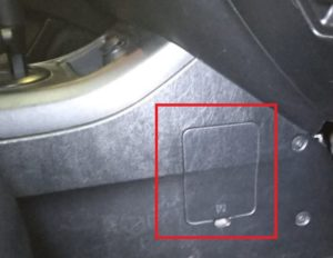
It is located under the dashboard (lower part of the dashboard), on the passenger side and is covered by a protective cover. To access it, simply pull the special notch in the cover with a flat screwdriver.
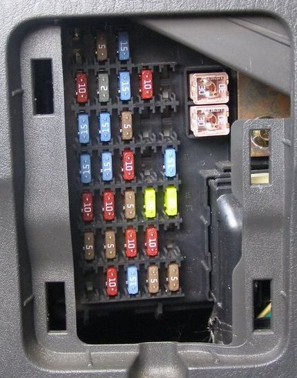
Option 1
Photo example

Scheme

Description
| 1 | 5A Electro-pneumatic valve of the fuel vapor accumulator |
| 2 | 5A Fan relay, rear window heating |
| 3 | 10A Rear door window wiper and washer motor |
| 4 | 10A All-wheel drive system control unit, instrument cluster |
| 5 | 5A ABS and SRS control unit |
| 6 | 10A Hazard warning lights, reversing lights |
| 7 | 10A Transponder signal amplifier, SRS control unit |
| 8 | 10A Instrument cluster, selector lock relay |
| 9 | 3A Engine control unit and automatic transmission relay, fan relay, air conditioning relay |
| 10 | 20A Windshield wiper motor, windshield washer motor, wiper intermittent relay |
| 11 | 10A Starter relay, ignition key lock solenoid valve |
| 12 | 5A Radio and clock |
| 13 | Reserve |
| 14 | 20A Cigarette lighter |
| 15 | 15A Dimensions, local lighting lamps, trailer wiring relay |
| 16 | 10A Instrument cluster, electric mirrors, electrical control unit |
| 17 | 15A Hatch |
| 18 | 5A Instrument cluster and instrument panel switch illumination |
| 19 | 10A Subwoofer |
| 20 | 15A Turn signals, turn signal indicators, hazard warning lights |
| 21 | 10A Trailer marker lights |
| 22 | 15A Reserve |
| 23 | 15/20A Audible signal |
| 24 | 15A Brake lights, ABS control unit, engine and automatic transmission control unit, automatic transmission gear shift solenoid valves |
| 25 | 30A Electric window regulator |
| 26 | 30A Central locking, electrical control unit, electric seats |
| 27 | 10A Radio, instrument cluster, interior lighting |
| ACC | Relay for installing additional equipment |
Fuse number 14 at 20A is responsible for the interior cigarette lighter.
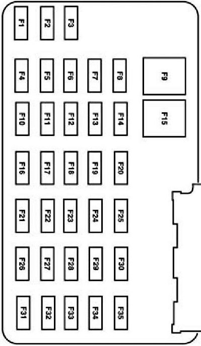
Option 2
Photo
Scheme
Marking
| 1 | 15A Trailer lamps |
| 2 | 5A Radio (backlight) |
| 3 | 15A Front and rear parking lights |
| 4 | 10A Ignition switch |
| 5 | 2A Automatic transmission control unit relay, fuel pump relay, fan relay, #2 high/low fan speed |
| 6 | 15A Additional brake light lamps, brake lights, engine and automatic transmission control unit, ABS, cruise control |
| 7 | 10A Instrument cluster, OBD diagnostic connector, radio, electric side mirrors |
| 8 | 15A Fog lights |
| 9 | 30A Central locking, electric seats |
| 10 | 15A Side mirror heater |
| 11 | 15A Hatch |
| 12 | 15A Radio |
| 13 | Reserve |
| 14 | Reserve |
| 15 | 30A Power window actuator |
| 16 | 15A Subwoofer |
| 17 | 15A Dipped beam |
| 18 | 18A All-wheel drive system |
| 19 | 15A Anti-theft system |
| 20 | 20A Audible signal |
| 21 | 10A Rear door window wiper and washer motor |
| 22 | 10A Interior rear-view mirror, instrument cluster |
| 23 | 5A Radio (power) |
| 24 | 20A Cigarette lighter |
| 25 | 20A Windshield washer and wiper motor |
| 26 | 5A Air conditioner |
| 27 | 5A Cruise control system switch |
| 28 | 10A Instrument cluster |
| 29 | 10A Reversing lights |
| 30 | Reserve |
| 31 | Reserve |
| 32 | 10A Selector lock relay |
| 33 | 15A SRS control unit, front passenger airbag off indicator, front seat passenger presence sensor |
| 34 | 5A ABS unit, cruise control |
| 35 | 5A Heated seats, four-wheel drive |
Fuse number 24 at 20A is responsible for the front cigarette lighter.
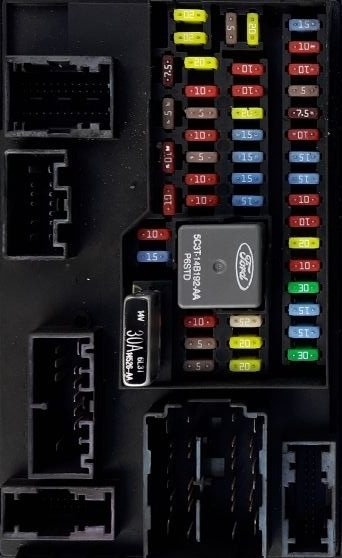
Option 3
Photo – example
Scheme
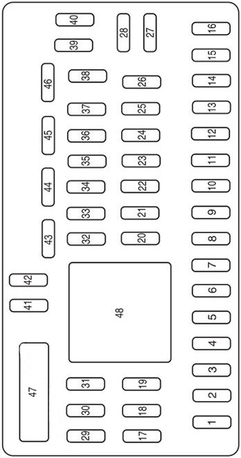
Appointment
| 1 | 30A Not used (spare) |
| 2 | 15A Brake switch |
| 3 | 15A Synchronization module |
| 4 | 30A Luke |
| 5 | 10A Keyboard backlight, brake shift interlock (BSI), SPDJB |
| 6 | 20A Turn signals, brake lights |
| 7 | 10A Low beam headlights (left) |
| 8 | 10A Low beam headlights (right) |
| 9 | 15A Interior lighting |
| 10 | 15A Backlight |
| 11 | 10A All-wheel drive |
| 12 | 7.5A Power mirror switch |
| 13 | 5A Not used (spare) |
| 14 | 10A FCIM (button radio), satellite radio, front panel display module |
| 15 | 10A Climate control |
| 16 | 15A Not used (spare) |
| 17 | 20A All engine power supplies, liftgate unlocking, lift glass unlocking |
| 18 | 20A Seat heating |
| 19 | 25A Rear wiper |
| 20 | 15A Diagnostic connector |
| 21 | 15A Fog lights |
| 22 | 15A Park lights |
| 23 | 15A High beam headlights |
| 24 | 20A Signal Relay |
| 25 | 10A Emergency alarm |
| 26 | 10A Combination dashboard |
| 27 | 20A Ignition switch |
| 28 | 5A Radio |
| 29 | 5A Instrument cluster |
| 30 | 5A Not used (spare) |
| 31 | 10A Limiter Control Module |
| 32 | 10A Not used (spare) |
| 33 | 10A Not used (spare) |
| 34 | 5A Anti-lock braking system (ABS) |
| 35 | 10A All-wheel drive, Electric power steering (EPAS) module, Parking assist module |
| 36 | 5A PATS transceiver |
| 37 | 10A Climate control |
| 38 | 20A Subwoofer / amplifier (radio) |
| 39 | 20A Radio, radio amplifier (for navigation only) |
| 40 | 20A Front cigarette lighter |
| 41 | 15A Driver/Passenger Door Switches, Auto Dimming Mirror, Compass, Exterior Lights, Roof |
| 42 | 10A Not used (spare) |
| 43 | 10A Rear wiper logic, Seat heating relay, Instrument cluster |
| 44 | 10A Not used (spare) |
| 45 | 5A Front wiper, blower motor relay |
| 46 | 7.5A OCS (restrictions), PADI (restrictions) |
| 47 | 30A Automatic window switch |
| 48 | Delayed access relay |
Fuse number 40 at 20A is responsible for the front cigarette lighter.
The rear and additional sockets, relevant for all generations, can also be controlled by fuses located in the block under the hood. They are indicated on the diagrams as – PWR1 and PWR2
Relay
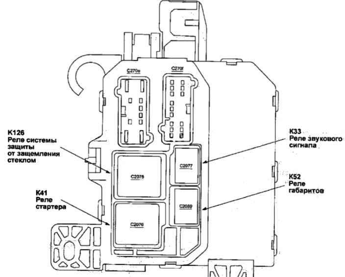
On the back of the unit there may be some relays, such as:
- Glass pinch protection relay
- Starter relay
- Dimension relay
- Horn relay
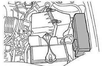
Block under the hood
It is located on the left side, next to the battery, under a protective cover. On the back of which the current designation of the fuses and relays will be written.
Option 1
Scheme
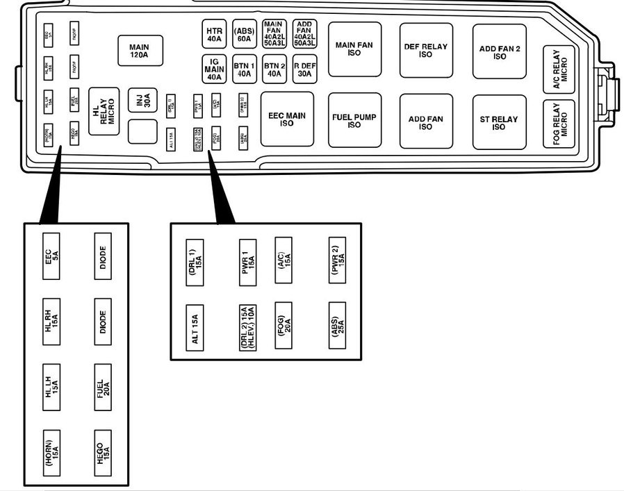
Transcript
| Horn | 15A Audible signal |
| H/LLH | 15A Left headlight |
| H/L HR | 15A Right headlight |
| EEC | 5A Engine control system |
| SOUTH | 15A Fuel injection system |
| FUEL | 20A Fuel pump |
| DIODE | Diode |
| DIODE | Diode |
| H/L RELAY MICRO | Headlight relay |
| INJ | 30A Engine management system, mass air flow sensor, idle speed control valve |
| MAIN | 120A Main fuse |
| ALL | 15A Generator |
| (DRL) | 15A Daytime running light system |
| (DRLZ) | 15A Daytime running light control unit |
| (Stable) | 10A Headlight leveling |
| PWR1 | 15A Socket for connecting additional devices |
| FOG | 20A Fog lights |
| A/C | 15A Air conditioner compressor clutch |
| (ABS) | 25A Anti-lock brake system |
| PWR2 | 15A Socket for connecting additional devices |
| IG MAIN | 40A Starter circuit |
| HTR | 40A Fan motor, fan motor relay |
| BTN 1 | 40A Radio, cigarette lighter, instrument cluster, electric mirrors |
| (ABS) | 60A ABS pump motor |
| BTN 2 | 40A Radio, instrument cluster, cruise control, electric seat adjustment, horn |
| MAIN FAN | 40/50A Main fan |
| RDEF | 30A Rear door glass heating |
| ADD FAN | 40/50A Additional fan |
| EEC MAIN ISO | Engine control system relay |
| FUEL PUMP ISO | Fuel pump relay |
| MAIN FAN ISO | Low fan speed relay (YF motor) High fan speed relay #1 (AJ motor) |
| ADD FAN ISO | High fan speed relay (YF motor) Low fan speed relay (AJ motor) |
| DEF RELAY ISO | Rear door glass heater relay |
| ST RELAY ISO | Starter relay |
| ADD FAN 2 ISO | High fan speed relay #2 (AJ motor) Medium fan speed relay (YF motor) |
| FOG RELAY MICRO | Fog light relay |
| A/C RELAY MICRO | Air conditioner compressor clutch relay |
Option 2
Scheme
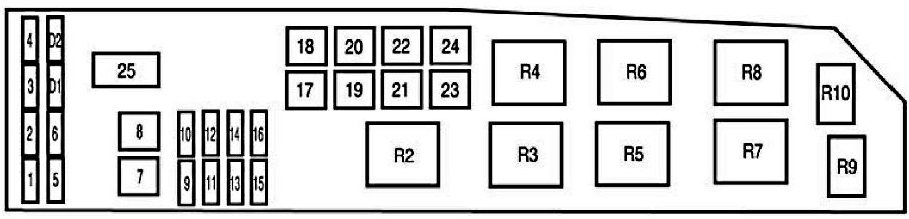
Description of the scheme
| 1 | 25A Instrument panel fuse |
| 2 | 25A Headlights |
| 3 | 25A High beam headlights, turn signals, interior lighting, headlights |
| 4 | 5A System for delaying power supply to some circuits after ignition is turned off |
| 5 | 15A Oxygen sensor heater |
| 6 | 20A Fuel Pump |
| 7 | 40A RUN/ACC Relay – Cigarette lighter, windshield and rear door wipers |
| 8 | 30A Engine control unit and automatic transmission, injectors and coils |
| 9 | 15A Generator |
| 10 | 30A Seat heating |
| 11 | 10A Engine and automatic transmission control unit |
| 12 | 20A Sockets for connecting additional equipment |
| 13 | 20A Fog lights (headlights/lamps) |
| 14 | 15A Air conditioner compressor electromagnetic clutch, air conditioner relay |
| 15 | 30A Anti-lock brake system |
| 16* | 25A Instrument panel fuse |
| 17 | 50A Starter circuit |
| 18 | 40A Fan motor |
| 19 | 40A Additional relay – subwoofer, all-wheel drive system, low beam headlights |
| 20 | 60A Anti-lock brake system |
| 21 | 40A Horn, additional brake light, instrument cluster, central locking and electric seats |
| 22 | 40/50A Radiator fan |
| 23 | 40A Rear door glass heater, parking light relay |
| 24 | 40/50A High/Low Speed Fan |
| 25 | Shunt |
| R2 | Engine control unit and automatic transmission relay |
| R3 | Fuel pump relay |
| R4 | Radiator fan relay |
| R5 | Relay #1 high/low fan speed |
| R7 | Starter relay |
| R8 | Relay #2 high/low fan speed |
| R9 | Fog light relay (headlights/lamps) |
| R10 | Air conditioner relay |
| D1 | Starter diode |
| D2 | Air conditioner diode |
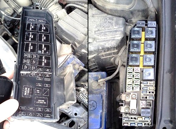
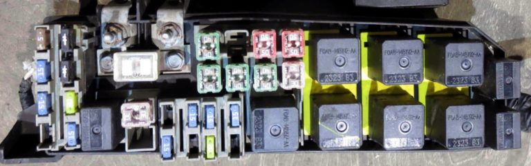
Option 3
Photo – example
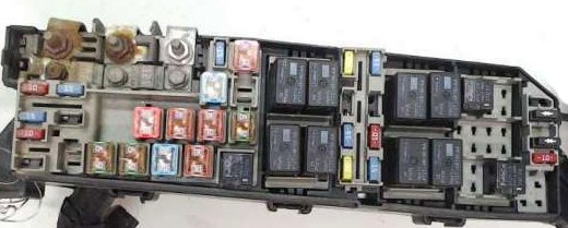
Scheme
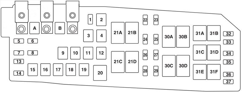
Appointment
| A | 80A Electronic Power Steering (EPAS) Module |
| B | 125A Fuse panel in the passenger compartment |
| 1 | 15A Heated mirror |
| 2 | 30A Rear heater |
| 3 | 20A Rear sockets (center console) |
| 4 | Reserve |
| 5 | 10A Powertrain Control Module (PCM) – supports power, PCM relays, canister ventilation |
| 6 | 15A Generator |
| 7 | 15A Hatch |
| 8 | 20A Trailer parking lights |
| 9 | 50A Anti-lock braking system (ABS) |
| 10 | 30A Front wipers |
| 11 | 30A Starter |
| 12 | 40A Fan motor |
| 13 | 10A Air conditioner clutch |
| 14 | 15A Trailer headlight bulbs |
| 15 | Reserve |
| 16 | 40A Cooling fan 1 |
| 17 | 40A Cooling fan 2 |
| 18 | 20А ABS |
| 19 | 30A Power seats |
| 20 | Air conditioner drive relay |
| 21A | Rear window defroster relay |
| 21B | Fuel relay |
| 21C | Fan relay |
| 21D | PCM relay |
| 22 | 20A Fuel pump |
| 23 | 15A Fuel injectors |
| 24 | Not used |
| 25 | 5A ABS |
| 26 | 15A Ignition coils |
| 27 | 10A powertrain component fault indicator lamp |
| 28 | 20A powertrain component fault indicator lamp |
| 29 | 15А PCM |
| 30A | Cooling fan relay 1 |
| 30B | Starter relay |
| 30C | Cooling fan main relay |
| 30D | Cooling fan relay 2 |
| 31A | Taillight relay |
| 31B | Not used |
| 31C | Left turn trailer relay |
| 31D | Trailer right turn relay |
| 31E | Trailer |
| 31F | Lock relay |
| 32 | Not used |
| 33 | Air conditioner diode |
| 34 | Starter diode |
| 35 | Start/stop, reverse lights, rear heater relay |
| 36 | Reserve |