Audi A4 (B8) – the fourth generation of the Audi A4 car. It was produced in 2007, 2008, 2009, 2010, 2011, 2012, 2013, 2014 and 2015. This publication presents a description of the fuses and relays of the Audi A4 B8 with diagrams and photos of the blocks. Let’s highlight the fuse responsible for the cigarette lighter.
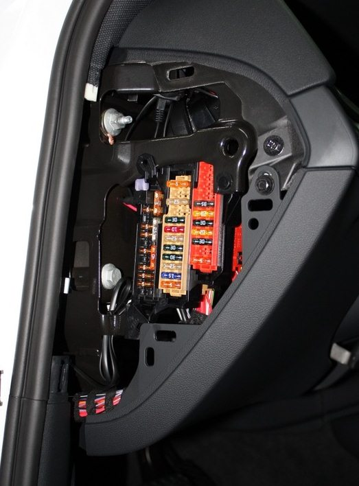
Fuse board on the left dashboard
To access the fuses, open the door and remove the cover. It will look something like this. An example of access is in our video at the end of the article.
Description for Audi A4 B8 cars until 2009.
| 1 | (5A) Power steering control unit |
| 2 | (5A) Clutch pedal position sensor |
| 3 | (5A) Garage door remote control system control unit |
| 4 | (10A) Marking tracking system control unit |
| 5 | (5A) Heater inlet air purity sensor |
| 6 | (5A) Right headlight |
| 7 | (5A) Left headlight |
| 8 | (5A) On-board network control unit |
| 9 | (5A) Interior rearview mirror with dimming function |
| 10 | (5A) Gear shift control unit |
| 11 | (5A) Windshield washer nozzle heaters |
| 12 | (5A) Air conditioning system |
| 13 | (5A) Cooling system pump motor |
| 14 | (5A) Clutch pedal position sensor |
| 15 | (20A/25A) Fuel pump control unit |
| 16 | (5A) Cooling system pump motor |
| 17 | (30A) On-board network control unit |
| 18 | (10A) ABS electronic control unit |
| 19 | (25A) Audible signal |
| 20 | (30A) Door function control units |
| 21 | (30A) Windshield wiper motor |
| 22 | (25A) ABS electronic control unit |
| 23 | (15A) Door function control units |
| 24 | (5A) Rain and light sensor |
| 25 | – |
| 26 | – |
| 27 | (10A) Electric seat drive |
| 28 | (35A) Power steering control unit |
| 29 | (5A) Antenna signal amplifier |
| 30 | (35A) On-board network control unit |
| 31 | (20A) On-board network control unit |
| 32 | (30A) On-board network control unit |
| 33 | (20A) Sunroof electric drive control unit |
| 34 | (30A) On-board network control unit |
| 35 | (20A) Sunshade |
| 36 | (5A) Anti-theft system |
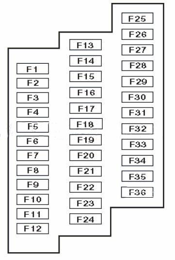
Description for Audi A4 B8 cars after 2009.
| F1 | (5A) Power steering control unit |
| F2 | – |
| F3 | (5A) Garage door remote control system control unit |
| F4 | (10A) Marking tracking system control unit |
| F5 | (5A) Heater inlet air purity sensor |
| F6 | (5A) Right headlight |
| F7 | (5A) Left headlight |
| F8 | (5A) on-board network control unit |
| F9 | (5A) Distance control unit (cruise control) |
| F10 | (5A) Clutch pedal position sensor, clutch sensor control unit, |
| F11 | (5A) Windshield washer nozzle heaters |
| F12 | (5A) Air conditioning system |
| F13 | (5A) Telephone jack |
| F14 | (5A) Hazard warning light button, airbag control unit, seat occupancy recognition, |
| F15 | (25A) ABS electronic control unit |
| F16 | (40A) Starter |
| F17 | (5A) Interior rearview mirror with dimming function |
| F18 | (5A) Clutch pedal position sensor |
| F19 | (20A/25A) Fuel pump control unit |
| F20 | (10A) Cooling system pump motor |
| F21 | (15A/30A) |
| F22 | (10A) ABS electronic control unit |
| F23 | (25A) Audible signal |
| F24 | (30A) Door function control units |
| F25 | (30A) Windshield wiper motor |
| F26 | (25A) ABS electronic control unit |
| F27 | (15A) Door function control units |
| F28 | (5A) Rain and light sensor. |
| F29 | – |
| F30 | – |
| F31 | (10A) Electric seat drive |
| F32 | (35A) Power steering control unit |
| F33 | – |
| F34 | (35A) |
| F35 | (20A) |
| F36 | (30A) |
| F37 | (20A) Sunroof electric drive control unit |
| F38 | (30A) |
| F39 | (20A) Sunshade |
| F40 | (5A) Anti-theft system |
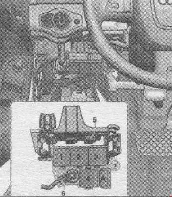
Fuse board on the instrument panel on the right
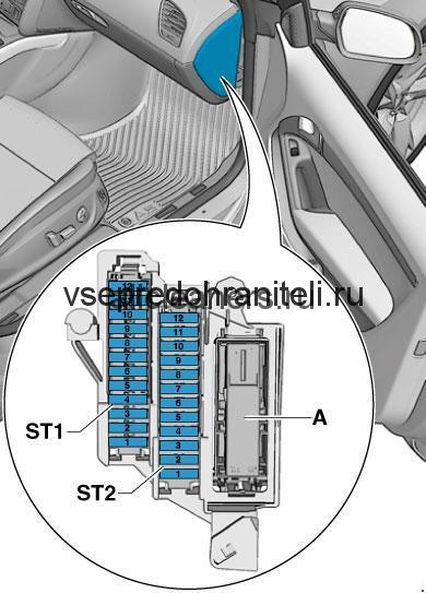
Decoding the scheme
| 1 | ST1 |
| 2 | |
| 3 | |
| 4 | |
| 5 | (5A) Steering column electrical control unit |
| 6 | (5A) Electronic Stability Program (ESP) switch |
| 7 | (5A) Diagnostic Connector (DLC) |
| 8 | (5A) CAN data bus, gateway control unit |
| 9 | (5A) Coolant heater |
| 10 | |
| 11 | |
| 12 | |
| 1 | (5A) Audio system – ST2 |
| 2 | (5A) Multifunction switch |
| 3 | (5A/20A) |
| 4 | (5A) Instrument cluster control unit |
| 5 | (5A) CAN data bus, gateway control unit |
| 6 | (5A) Remote control system for central locking and engine start (keyless entry and start) |
| 7 | (5A) Headlight switch |
| 8 | (40A) Air conditioner/heater fan motor control unit |
| 9 | (5A) Steering column lock control unit |
| 10 | (10A) Air conditioning electronic control unit |
| 11 | (10A) Diagnostic Connector (DLC) |
| 12 | (5A) Steering column electrical control unit |
Additional units in the Audi A4 B8 cabin
6-pin rack-mount switch block
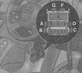
Located in the driver’s footwell, behind the side trim.F. Thermal fuse 1 per. wire. passage. -S46-, 15 AG. Thermal fuse 1 per. driver’s seat. -S44-
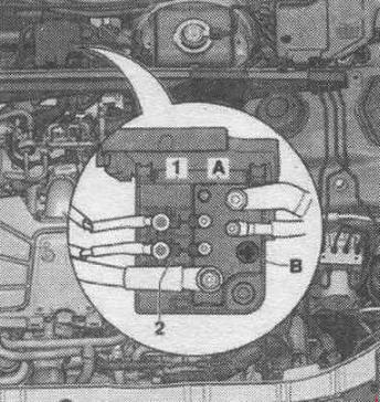
Relay and fuse block from a used on-board network
The installation location of the relay/fuse block from the on-board network is under the panel on the driver’s side.
DescriptionA. Fuse 1 used ABS -S123-, 40 A1. Not used2. Circulation pump relay -L 60-2. Horn relay -J413-2. Vacuum pump relay -J318-2. Relay for interior rearview mirror with automatic dimming function -J910-3. Power relay terminal 15. J329-4. Used remote control for taxi anti-theft alarm -J601-
Fuse and relay blocks in the engine compartment
Block in the center of the drain box
Description
| Number | Value | Component |
| 1 | 40A, 60A | 400W Fan Control System. 600W Fan Control System |
| 2 | 40A | 400 Watt Fan Control |
Switchboard fuse board
Scheme
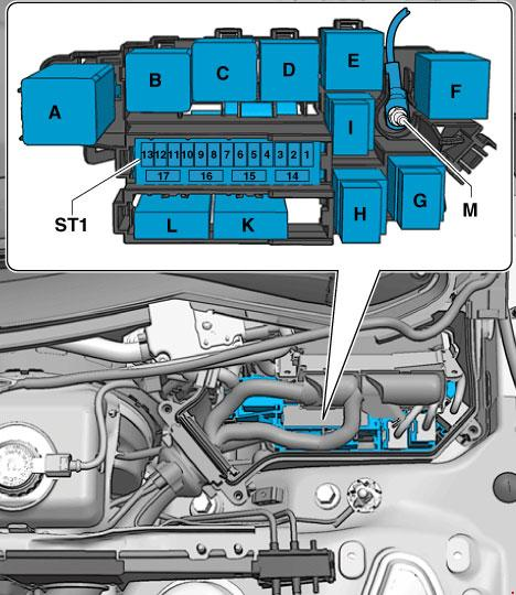
Purpose of board elements
- A. Used automatic glow plug system (before 2011)
- A. Engine component power relay
- B. Starter relay (up to 2011)
- B. Relay 2 starter
- C. Secondary air pump relay
- D. Power relay cl. 30 (until 2011)
- D. Motronic system power relay
- E. Fuel pump relay
- E. Auxiliary fuel pump relay
- E. Coolant recirculation relay after engine shutdown
- E. Relay for auxiliary cooling system pump
- E. Transmission cooling circuit relay
- E. Engine Component Power Relay 2
- F. not used
fuses for cars before October 2011
| Number | Par | Appointment |
| 1 | 15 A | Automatic transmission control unit. Mechatronics for dual clutch transmissions |
| 2 | 5 A | Engine oil level and temperature sensor |
| 3 | 5 A | Engine control unit. Air flow meter |
| 4 | 5A | Engine control unit |
| 5 | 10A, 15A, 20A | Air flow meter. Automatic glow plug control unit. Secondary air pump relay. Low heating power relay. High heating power relay. Boost pressure limit solenoid valve. Crankcase ventilation system heating resistor. Adsorber solenoid valve 1. Secondary air supply control valve. Left electrohydraulic engine mount solenoid valve Right electrohydraulic engine mount solenoid valve Intake manifold geometry change system valve. Air filter bypass flap valve -. Fuel pressure regulator. Fuel metering valve. Secondary air supply control valve 2-. Exhaust gas recirculation system radiator switch. Oil pressure reducing valve. Fuel system diagnostic pump |
| 6 | 15 A | Engine control unit |
| 7 | 10A, 15A | Actuator 1 of the valve timing system. Actuator 9 of the valve timing system. Solenoid valve for limiting the boost pressure. Solenoid valve 1 of the adsorber – solenoid valve of the left electrohydraulic engine mount. Solenoid valve of the right electrohydraulic engine mount Valve 1 of the valve timing system. Valve 2 of the valve timing system. Charge air recirculation valve. Fuel pressure regulator-. Fuel metering valve. Intake manifold flap valve -N316-. Valve 1 of the exhaust valve timing regulator. Valve 2 of the exhaust valve timing regulators. Climatronic coolant shut-off valve. Oil pressure relief valve. Fuel system diagnostic pump Charge air cooling pump |
| 8 | 10A, 5A, 20A | Exhaust gas recirculation system radiator pump-V400-. Ignition coil 1 with output stage. Ignition coil 2 with output stage. Ignition coil 3 with output stage. Ignition coil 4 with output stage. Ignition coil 5 with output stage. Ignition coil 6 with output stage |
| 9 | 5A, 15A, 20A | Additional fuel pump relay. Lambda probe 1 heater after catalytic converter. Lambda probe 2 heater after catalytic converter |
| 10 | 10A, 15A | Lambda probe heating element. Lambda probe heating element 2. Lambda probe heating element 1 after the catalyst |
| 11 | 5 A | Radiator fan control unit. Radiator fan control unit 2 |
| 12 | 5 A | Air flow meter. Mechatronik automatic transmission control unit for dual clutch transmissions |
for cars manufactured from October 2011
| Number | Par | Appointment |
| 1 | 15 A | Automatic transmission control unit – Mechatronik for dual clutch transmissions |
| 2 | 5 A | Engine oil level and temperature sensor |
| 3 | 5 A | Engine control unit |
| 4 | 5 A | Engine control unit |
| 5 | 10A, 5A | Air flow meter. Fuel pressure regulator. Fuel metering valve |
| 6 | 15 A | Engine control unit – Injector 2 cylinders 1, 2, 3, 4 |
| 7 | actuator 1, 2, 3, 4, 5, 6, 7, 8 of the valve timing system. Boost pressure limit solenoid valve. Adsorber solenoid valve 1. Left electrohydraulic engine mount solenoid valve. Right electrohydraulic engine mount solenoid valve. Valve 1 of the valve timing system. Valve 2 of the valve timing system. Charge air recirculation valve. Fuel pressure regulator. | |
| 8 | 10A, 15A, 5A | NOx sensor 2. NOx sensor 2 control unit |
| 9 | 5 A | Voltage stabilizer. Engine control unit |
| 10 | 10A, 15A | Lambda probe heating element |
| 11 | 5 A | Radiator fan control unit |
| 12 | 5 A | Automatic transmission control unit |
| 13 | not used | |
| 14 | 5A, 20A | Engine component power relay 2. Ignition coil 1 with output stage. |
| 15 | 5 A | Power steering control unit |
| 16 | 15 A | Thermostat of the parametric engine cooling system. Control unit of the automatic glow plug system |
| 17 | 15 A | Lambda probe heating element after the catalytic converter |
Fuse box in the trunk of an Audi A4 B8
The unit is located behind the right side panel. The description of the elements may differ from those given.
Scheme
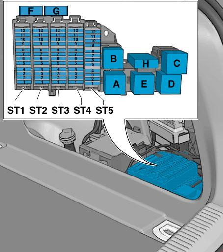
Decoding for cars before 2010 .
| A | Sedan: Not used |
| B | – |
| C | Rear window heater relay |
| D | – |
| AND | Accessory power connector relay |
| 1 | (30A) Trunk lid control unit |
| 2 | – |
| 3 | (30A) Trunk lid control unit |
| 4 | (5A) Plug connector |
| 5 | – |
| 6 | – |
| 7 | – |
| 8 | – |
| 9 | – |
| 10 | – |
| 11 | – |
| 12 | – |
| 13 | (5A) Tire pressure monitoring system control unit |
| 14 | (15A) Trailer electrical control unit |
| 15 | (20A) Trailer electrical control unit |
| 16 | (20A) Trailer electrical control unit |
| 17 | (5A) Electric brake control unit |
| 18 | (15A) Suspension control unit |
| 19 | (30A) Electric parking brake control unit |
| 20 | (30A) comfort system |
| 21 | (35A) 4WD electronic control unit |
| 22 | (30A) comfort system |
| 23 | (20A) comfort system |
| 24 | (5A) vehicle location management system |
| 25 | (15A/30A) Accessory power connector |
| 26 | (15A) Seat heating control unit |
| 27 | (7.5A) navigation system/radio |
| 28 | (30A) Audio system |
| 29 | (5A) Multifunction display control unit |
| 30 | (30A) Auxiliary heater control unit |
| 31 | (30A) Electric parking brake control unit |
| 32 | (30A) Seat heater |
| 33 | (30A) Door function control units |
| 34 | (5A) Auxiliary heater remote control receiver |
| 35 | (15A) Door function control units |
| 36 | (5A) Rear view camera control unit |
| 37 | (15A) Accessory power connector |
| 38 | (15A) Accessory power connector |
| 39 | (15A) Accessory power connector |
| 40 | (15A) Cigarette lighter |
| 41 | (5A) Self-parking system control unit |
| 42 | – |
| 43 | (5A) Distance control unit (cruise control) |
| 44 | (15A) Rear window wiper motor |
| 45 | (5A) Electric brake control unit |
| 46 | (5A) Lane change assist control unit |
| 47 | (5A) Seat heater |
| 48 | (5A) Hazard warning light, airbag control unit |
| 49 | – |
| 50 | – |
| 51 | (10A/15A/25A) |
| 52 | (10AL5A) Special automotive equipment |
| 53 | (5A/15A) Special automotive equipment |
| 54 | (10A) Special automotive equipment |
| 55 | (5A/20A) Special automotive equipment |
| 56 | (10A) Special automotive equipment |
| 57 | (10A) Accessory power connector |
| 58 | (10A) Special automotive equipment |
| 59 | (10A) Special automotive equipment |
| 60 | – |
| 61 | (40A) Rear window heater |
Decoding for cars from 2010 onwards.
| Number | Ampere | Function/component |
| 1 | not used | |
| 2 | not used | |
| 3 | 15A. 25A | Alarm system control unit |
| 4 | 15 A | Alarm system control unit |
| 5 | 5A, 15A | Special signal control panel, Alarm system control unit |
| 6 | FOR | Special signal control panel. Alarm system control unit, Tachograph control unit. Plug connector, 3-pin. Fault memory |
| 7 | 20 A | Control unit for special vehicles |
| 8 | 10 A | Accident memory |
| 9 | 10 A | 12 V socket |
| 10 | 10 A | Radio isolation relay, radio relay |
| 11 | 10 A | Radio isolation relay, radio relay |
| 12 | not used | |
| 13 | 30 A | Control unit 2 luggage compartment lid- |
| 14 | 15 A | Trailer recognition control unit |
| 15 | 20 A | Trailer recognition control unit |
| 16 | 20 A | Trailer recognition control unit |
| 17 | 5 A | AUTO HOLD button |
| 18 | 15 A | Electronic shock absorber stiffness adjustment control unit |
| 19 | 30 A | Electromechanical parking brake control unit |
| 20 | 30 A | Central control unit for comfort systems |
| 21 | 35 A | All-wheel drive system control unit |
| 22 | 30 A | Central control unit for comfort systems |
| 23 | 20 A | Central control unit for comfort systems |
| 24 | 5 A | Vehicle location system interface control unit |
| 25 | 30 A | Trunk lid control unit |
| 26 | 15 A | Right front seat ventilation control unit |
| 27 | 40 A | Radio. Telephone receiver-TV tuner. Mobile phone amplifier. Telephone holder-. Plug connector, 18-pin |
| 28 | 40 A | Voltage stabilizer |
| 29 | 30 A | Inverter with socket, 12 V |
| 30 | 30 A | Auxiliary heater control unit |
| 31 | 30 A | Electromechanical parking brake control unit |
| 32 | 30 A | Rear left heated seat adjustment switch. Rear right heated seat adjustment switch |
| 33 | 30 A | Right door |
| 34 | 5 A | Autonomous heater receiver |
| 35 | 15 A | Right door |
| 36 | 30 A | Additive dosing system control unit |
| 37 | 15 A | 12 V socket |
| 38 | 15 A | 12 V socket. Inverter with socket, 12 V – 230 V |
| 39 | 15 A | 12 V socket |
| 40 | 15 A | Cigarette lighter |
| 41 | not used | |
| 42 | 5 A | Plug connector, 2-pin, in the backrest of the driver’s seat. Plug connector, 2-pin, in the backrest of the driver’s seat |
| 43 | 7.5 A | Parking autopilot control unit |
| 44 | 15 A | Rear window wiper motor |
| 45 | 5 A | Electromechanical parking brake button |
| 46 | 5 A | Lane change assistant control unit 2 |
| 47 | 5 A | Rear left heated seat adjustment switch |
| 48 | 5 A | Trailer recognition control unit. All-wheel drive system control unit. Voltage stabilizer. Electromechanical parking brake control unit |
| 49 | not used | |
| 50 | not used | |
| 51 | 20A, 30A | Digital audio system control unit. Radio |
| 52 | 7.5A | Electronic information system control unit |
| 53 | 5A, 7.5A | Navigation system control unit with CD drive. Radio. Telephone receiver -. TV tuner – Mobile phone amplifier. Telephone holder -. Plug connector, 18-pin |
| 54 | 5 A | Rear view camera control unit |
| 55 | 5 A | Mobile phone booster |
| 56 | not used | |
| 57 | not used | |
| 58 | not used | |
| 59 | not used | |
| 60 | not used | |
| 61 | 40 A | Rear window heating relay – rear window heater |
Fuse number 40 at 15A is responsible for the cigarette lighter.