Toyota Ractis 2nd generation was produced in 2010, 2011, 2012, 2013, 2014, 2015, 2016, 2017, 2018. During this time, the model was updated. In some countries it is known as Toyota Verso-S . In this publication you will find information about the location of electronic control units, a description of fuses and relays Toyota Ractis 2 (Toyota Verso-S) with block diagrams and their locations. Note the cigarette lighter fuse.

The arrangement of the blocks and the purpose of the elements in them may differ from the one shown. Check the purpose of the elements with your diagrams on the block cover.
Blocks in the cabin
Location
General layout
Left hand drive (LHD)
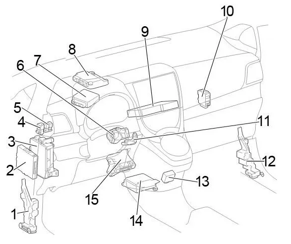
- Junction block
- LHD:
Engine Stop/Start ECU
without Stop/Start System: Power Management ECU - Fuse Box / Main Body ECU
- Heater relay (HTR)
- Relay block
- Steering lock actuator
- Power steering ECU
- Gearbox control unit
- Extension module
- Windscreen wiper relay
- Transponder key amplifier
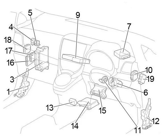
- Junction block
- Gearshift Lock ECU
- Central airbag sensor
- Air conditioner booster
- RHD: Engine Start/Stop ECU
- RHD: Power Management ECU
- RHD: Headlight range control unit
- RHD: Double Door Lock Control Relay
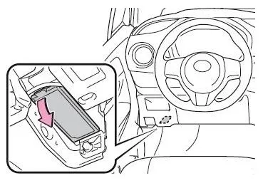
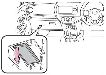
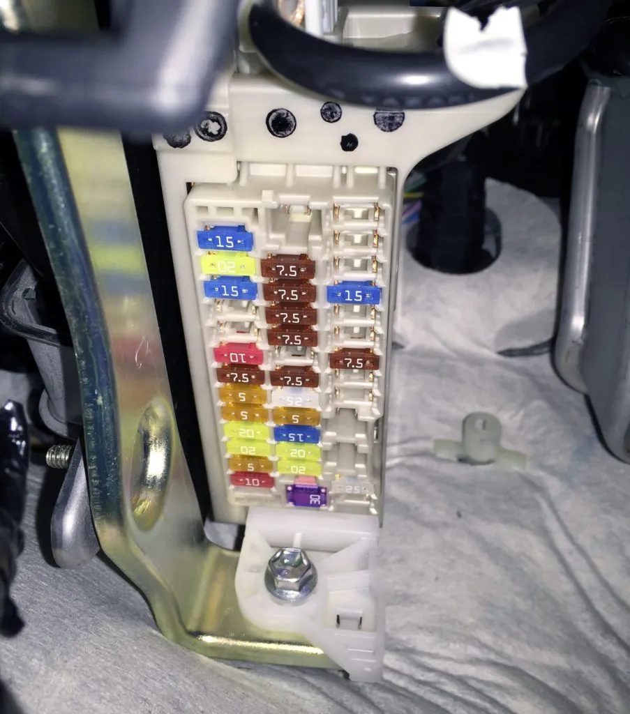
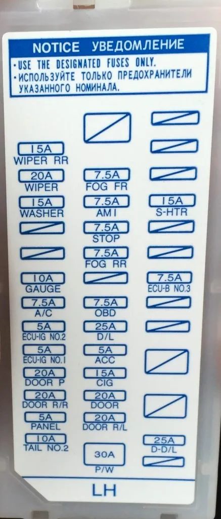
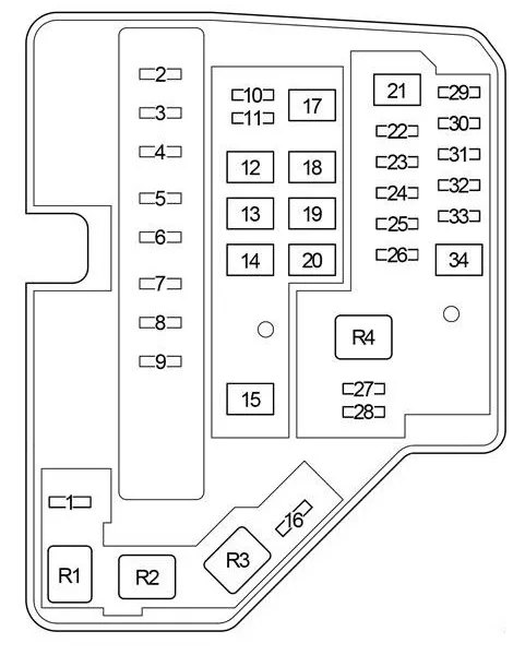
Fuse box
It is located under the instrument panel, covered with a protective cover.
Left hand drive
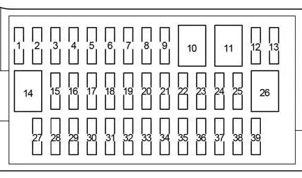
| 1 | – |
| 2 | – |
| 3 | – |
| 4 | 15A S-HTR – Heated Seats |
| 5 | – |
| 6 | – |
| 7 | 7.5A ECU-B NO.3 – Power Mirrors |
| 8 | 25A SHADE – Panoramic roof |
| 9 | – |
| 10 | – |
| 11 | – |
| 12 | 25A DD/L – Double Locking |
| 13 | – |
| 14 | – |
| 15 | 15A FOG FR – before June 2013: Front fog light |
| 15A FOG FR – from June 2013 (TMC): Front fog light (TMC – Toyota Motor Corporation) | |
| 7.5A FOG FR – since June 2013 (TMMF): Front fog light (TMMF – Toyota Motor Manufacturing France) | |
| 16 | 7.5A AM1 – Starting System |
| 17 | 7.5A STOP – Multiport fuel injection system / sequential multiport fuel injection system, VSC, brake light lamps, additional brake light |
| 18 | 7.5A FOG RR – Rear Fog Light |
| 19 | – |
| 20 | 7.5 OBD – Diagnostic connector |
| 21 | 25A D/L – Central locking, body electrical control unit |
| 22 | 5A ACC – Body electrical equipment control unit, electric mirrors, audio system, gear selector lock |
| 23 | 15A CIG – Socket (cigarette lighter) |
| 24 | 20A DOOR – Window lifters |
| 25 | 20A DOOR R/L – Window Lifters |
| 26 | 30A P/W – Window lifters |
| 27 | 15A WIPER RR – Rear Windscreen Wiper |
| 28 | 20A WIPER – Windscreen wiper |
| 29 | 15A WASHER – Glass washer |
| 30 | – |
| 31 | – |
| 32 | 10A GAUGE – Reverse Lights, Shift Lock, Audio, Charging System, Multiport Fuel Injection System/Sequential Multiport Fuel Injection System |
| 33 | 7.5A A/C – Air conditioning, heated rear window, heated mirrors |
| 34 | 5A ECU-IG NO.2 – VSC |
| 35 | 5A ECU-IG NO.1 – Cooling fan, rear window defogger, VSC, electric power steering, body electrical control unit, wireless control system, tire pressure monitoring system |
| 36 | 20A DOOR P – Window lifters |
| 37 | 20A DOOR R/R – Window lifters |
| 38 | 5A PANEL – Instrument cluster, instrument panel lighting, light switch |
| 39 | 10A TAIL NO.2 – Side light, number plate light |
Fuse number 23, 15A, is responsible for the operation of the cigarette lighter.
Relay block
Scheme
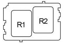
- R1 – Interior lighting (DOME CUT)
- R2 – Front fog light (FR FOG)
Additional elements
Scheme
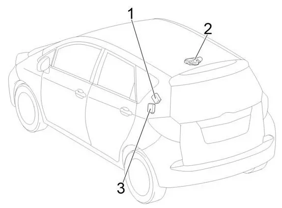
- Door control receiver
- Sliding roof drive gear
- Tire Pressure Warning System ECU and Receiver
Blocks under the hood
Location
General layout
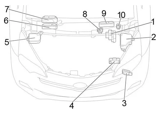
- Anti-skid control unit with drive
- Fuse and relay box
- Fuel pump ECU
- ECO Run Car Converter
- Fuse box #2
- Left hand drive 1NR-FE: ECM
- LHD 1ND-TV: ECM
- Fuse block
- RHD: ECM
- Glow Plug Relay
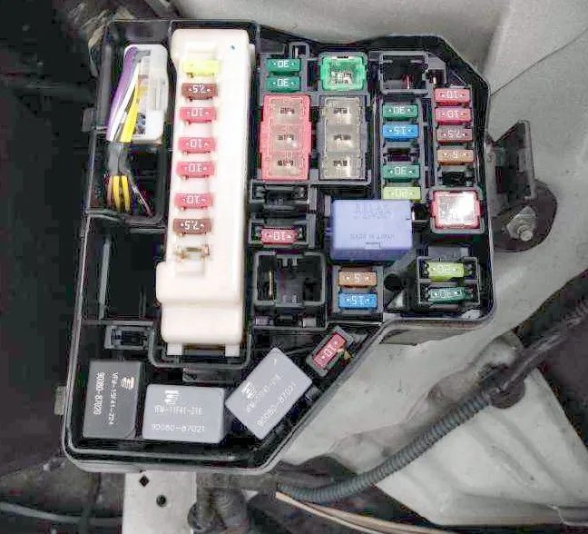
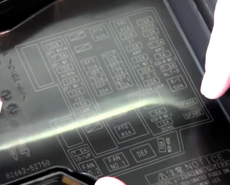
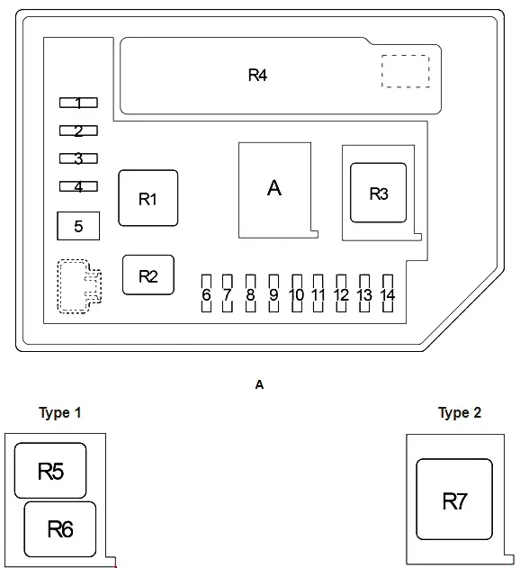
Fuse and relay box
Photo – example
| 1 | 7.5A ID/UP – Multi-port fuel injection system / sequential multi-port fuel injection system |
| 2 | 20A EFI MAIN – Gasoline: Multiport fuel injection system / Sequential multiport fuel injection system |
| 30A ECD MAIN – Diesel: Multiport fuel injection system / Sequential multiport fuel injection system, fuse “EFI NO.2” | |
| 3 | 7.5A EFI NO.3 – Multi-port fuel injection system / sequential multi-port fuel injection system |
| 4 | 10A HORN – Signal |
| 5 | 10A EFI NO.2 – Stop-Start System, Multiport Fuel Injection System / Sequential Multiport Fuel Injection System |
| 6 | Intelligent entry and start system, multi-port fuel injection system/sequential multi-port fuel injection system, multi-mode manual transmission, SRS airbag system, steering lock system, brake lights, stop and start system |
| 7 | 10A IG2 – Multi-port fuel injection system / sequential multi-port fuel injection system |
| 8 | 7.5A MET – Sensor and counters, Stop & Start system |
| 9 | – |
| 10 | – |
| 11 | 25A PWR HTR – Electric Heater, Multiport Fuel Injection System / Sequential Multiport Fuel Injection System |
| 12 | 50A EPS – Electric Power Steering |
| 13 | 30A ABS NO.2 – ABS, VSC |
| 14 | 30A DEF – Rear Window Defogger |
| 15 | 80A PTC – PTC Heater, Outside Rear View Mirror Heaters |
| 16 | – |
| 17 | 40A HTR – Air conditioning |
| 18 | – |
| 19 | 30A RDI FAN – Electric Cooling Fan |
| 20 | 50A ABS NO.1 – ABS, VSC |
| 21 | 40A BBC – Stop and Start System |
| 22 | 30A ST – Starting System |
| 23 | – |
| 24 | 25A D/L NO.2 – Electric door lock |
| 25 | 30A DCC – Fuses “DOME”, “ECU-B NO.1” |
| 26 | 20A STR LOCK – Steering lock system |
| 27 | 5A ECU-B NO.1 – Main Body ECU, Intelligent Entry & Start System |
| 28 | 15A DOME – Interior Lighting, Audio System, VSC |
| 29 | 10A ETCS – Multi-port fuel injection system / sequential multi-port fuel injection system |
| 30 | 10A HAZ – Direction indicators |
| 31 | 7.5A AM2 – Multi-port fuel injection system / sequential multi-port fuel injection system, intelligent entry and start system, starting system, multi-mode manual transmission |
| 32 | 5A ECU-B NO.2 – Gauge and meters, Power door lock, Wireless remote control, Stop & Start system, Smart entry and start system, Multi-mode manual transmission, Air conditioning system |
| 33 | – |
| 34 | 50A R/I – Fuses “EFI MAIN”, “ECD MAIN”, “EFI NO.2”, “EFI NO.3”, “IG2”, “IGN”, “MET”, “HORN” |
| R1 | Electric cooling fan (FAN) |
| R2 | Electric cooling fan (FAN) |
| R3 | Rear window heating (DEF) |
| R4 | Starting System (ST) with Stop and Start System; 1NZ-FE: Starting System (ST2) |
Fuse and Relay Box #2
Scheme
| 1 | – |
| 2 | 15A EU-DRL – Headlights |
| 3 | 10A S-HORN – Multi-port fuel injection system / sequential multi-port fuel injection system |
| 4 | 7.5A H-LP MAIN – Fuses “H-LP RH LO”, “H-LP LH LO” |
| 5 | 50A MMT – Multi-Mode Manual Transmission |
| 40A ST – with stop and start system; 1NZ-FE: Starting system | |
| 6 | 10A H-LP RH HI – Right headlight (high beam) |
| 7 | 10A H-LP LH HI – Left headlight (high beam), sensor and instruments |
| 8 | 10A H-LP RH LO – Halogen: Right Headlight (Low Beam) |
| 15A H-LP RH LO – HID: Right Headlight (Low Beam) | |
| 9 | 10A H-LP LH LO – Halogen: Left headlight (low beam), manual headlight range adjustment |
| 15A H-LP LH LO – HID: left headlight (low beam), manual headlight range adjustment | |
| 10 | – |
| 11 | – |
| 12 | – |
| 13 | – |
| 14 | – |
| R1 | Dimmer (DIM) |
| R2 | Daytime running lights / Anti-theft device (EU-DRL / S-HORN) |
| R3 | Headlights/Daytime Running Lights (H-LP/US-DRL) |
| R4 | Integration relay |
| R5 | 1NR-FE, 1ND-TV: Daytime running lights (DRL) |
| with stop-start system 1NZ-FE: Starter ((ST) until May 2014) | |
| R6 | 1NR-FE, 1ND-TV: (O/P MTR) |
| R7 | Multi-mode manual transmission (MMT) |
Power fuse box
Located on the positive terminal of the battery.
Scheme
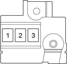
- 80A GLOW DC/DC – Multiport fuel injection system/sequential multiport fuel injection system
- 80A MAIN – Fuses: BBC”, “S-HORN”, “ST”, “D/L NO.2”, “DCC”, “STR LOCK”, “ETCS”, “HAZ”, “AM2”, “ECU-B NO.2”, “R/I”, “H-LP MAIN”, “H-LP RH HI”, “H-LP LH HI”, “H-LP RH LO”, “H-LP LH LO”, “MMT”
- ALT 120A – Charging System, Fuses:”PWR HTR”, “EPS”, “ABS NO.2”, “DEF”, “PTC”, “HTR”, “RDI FAN”, “ABS NO.1”, “TAIL NO.2”, “PANEL”, “DOOR R/R”, “DOOR P”, “ECU-IG NO.1”, “ECU-IG NO.2”, “A/C”, “GAUGE”, “WASHER”, “WIPER”, “WIPER RR”, “P/W”, “DOOR R/L”, “DOOR”, “CIG”, “ACC”, “D/L”, “OBD”, “FOG RR”, “STOP”, “AM1”, “FOG FR”, “DD/L”, “SHADE”, “S-HTR”