The Toyota Prius C hybrid car was produced in 2012, 2013, 2014, 2015, 2016, 2017, 2018, 2019. Also known as Toyota Aqua . The key difference between them is the side of the steering wheel. In this article, you will find a description of the fuses and relays of the Toyota Aqua with block diagrams and their locations. Let’s highlight the cigarette lighter fuse.
Block in the cabin
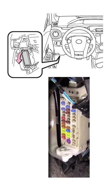
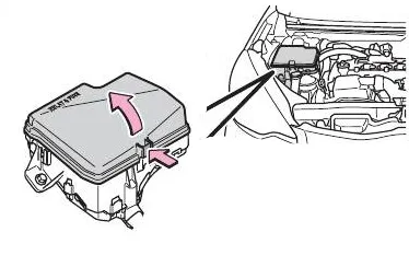
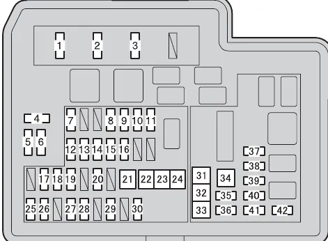
The fuse box is located on the left side under the instrument panel.
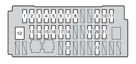
| 1 | 10A TAIL – Parking lights, side marker lights, tail lights, number plate lights, front fog lights, gauge and instruments |
| 2 | 5A PANEL – Instrument cluster illumination |
| 3 | 20A DOOR R/R – Rear Electric Window (Right Side) |
| 4 | 20A DOORP – Front window lifter (right side) |
| 5 | 5A ECU-IG NO.1 – Rear window defogger, tire pressure warning system, main body ECU, brake system, vehicle stability control system, power door lock system, smart key system |
| 6 | 5A ECU-IG NO.2 – Electric Power Steering |
| 7 | 7.5A HTR-IG – Air Conditioning System, PTC Heater |
| 8 | 10A GAUGE – Reversing lights, audio system, shift lock control system, sunroof, vehicle control and operating data recording, vehicle proximity alert system |
| 9 | 15A WASHER – Windscreen wipers and washer |
| 10 | 25A WIPER – Windscreen wipers and washer |
| 11 | 15A WIPER RR – Windscreen wipers and washer |
| 12 | 30A P/W – Window lifter |
| 13 | 20A DOOR R/L – Rear Electric Window (Left Side) |
| 14 | 20A DOOR D – Front Electric Window (Left Side) |
| 15 | 15A CIG – Socket, Cigarette Lighter |
| 16 | 5A ACC – Main Body ECU, Audio System, Outside Rear View Mirrors, Shift Lock Control System |
| 17 | 25A D/L – Electric door locking system |
| 18 | 7.5A OBD – On-Board Diagnostics |
| 19 | 7.5A STOP – Starter system, Shift lock control system, Vehicle proximity warning system, Brake system, Stop lights, High mounted stop light |
| 20 | 7.5A AM1 – Starter system |
| 21 | 15A FOG FR – Front fog lights |
| 22 | 25A S/ROOF – Hatch |
| 23 | 15A S/HTR – Seat heaters, air conditioning system |
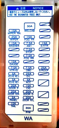
Fuse number 15 for 15A is responsible for the cigarette lighter.
Blocks under the hood
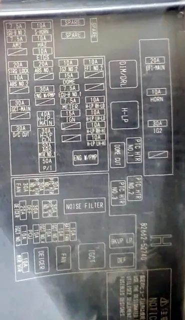
Main block
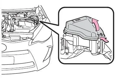
The main fuse and relay box is located under the hood on the right side.

| 1 | 20A EFI- MAIN – Multiport fuel injection system / sequential multiport fuel injection system, EFI NO.2 |
| 2 | 10A HORN – Signal |
| 3 | 30A IG2 #2, METER. IGN |
| 4 | 7.5A Spare Fuse |
| 5 | 15A Spare Fuse |
| 6 | 30A Spare Fuse |
| 7 | 10A EFI NO.2 – Multiport fuel injection system / sequential multiport fuel injection system |
| 8 | 10A H-LP RH-LO – Right headlight (low beam) |
| 9 | 10A H-LP LH-LO – Left headlight (low beam), sensor and instruments |
| 10 | 10A H-LP RH-HI – Right headlight (high beam) |
| 11 | 10A H-LP LH-HI – Left headlight (high beam), sensor and instruments |
| 12 | 10A IG2 NO.2 – Multiport fuel injection system/sequential multiport fuel injection system, steering switches, brake system, starter system, intelligent key system, occupant classification system, SRS airbag system |
| 13 | 15A DOME – Audio, Vehicle Management and Operational Data Recording, Main Body ECU, Personal Lights, Luggage Compartment Light |
| 14 | 7.5A ECU-B NO.1 – Main Body ECU, Smart Key System |
| 15 | 7.5A METER – Gauge and instrument panel |
| 16 | 15A IGN – Multi-port fuel injection system / sequential multi-port fuel injection system |
| 17 | 10A HAZ – Emergency Flashers |
| 18 | 10A ETCS – Multi-port fuel injection system / sequential multi-port fuel injection system |
| 19 | 20A ABS NO.1 – Brake system |
| 20 | 30A ENG W/PMP – Multi-port fuel injection system / sequential multi-port fuel injection system |
| 21 | 40A H-LP- MAIN – H-LP LH-LO, H-LP RH-LO, H-LP LH-HI, H-LP RH-HI, daytime running lights |
| 22 | 30A H-LP CLN – Headlight Cleaner |
| 23 | 30A ABS MTR NO.1 – Brake system |
| 24 | 50A P/I – EFI-MAIN, HORN, IG2 |
| 25 | 7.5A ECU-B NO.2 – Air conditioning system, pressure gauge and meters, occupant classification system, tire pressure warning system, starter system, smart key system, power door lock system |
| 26 | 7.5A AM2 – Starter System |
| 27 | 20A STRG LOCK – Steering Lock System |
| 28 | 10A ABS NO.2 – Brake system |
| 29 | 30A IGCT-MAIN – IGCT No. 2, IGCT No. 3, IGCT No. 4, PCU, BATT FAN |
| 30 | 30A D/C CUT – DOME, ECU-B No. 1 |
| 31 | 30A PTC HTR NO.1 – PTC Heater |
| 32 | 30A PTC HTR NO.2 – PTC Heater |
| 33 | 30A FAN – Electric cooling fan |
| 34 | 30A PTC HTR NO.3 – PTC Heater |
| 35 | 30A DEF – MIR HTR, rear window defroster |
| 36 | 20A DEICER – No circuit |
| 37 | 10A BATT FAN – Battery Cooling Fan |
| 38 | 10A IGCT NO.2 – Hybrid System |
| 39 | 10A IGCT NO.4 – Hybrid System |
| 40 | 10A PCU – Hybrid System |
| 41 | 10A IGCT NO.3 – Hybrid System |
| 42 | 10A MIR HTR – Exterior Rearview Mirror Heaters |
Additional block
Installed on the left side.
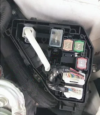
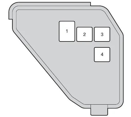
- DC/DC 100A Hybrid System
- ABS MTR NO.2 30 Brake system
- HTR 40 Air Conditioning System
- EPS 50 Electric Power Steering