Renault Magnum is a mainline tractor unit produced in four generations from 1990 to 2014 with different engine capacities. The most popular were the Renault Magnum dxi engines with a capacity of 440, 460 and 480 hp. In this publication, we will show a description of the fuses and relays of the Renault Magnum with block diagrams and their locations. Note the fuse responsible for the cigarette lighter.
The design of the blocks and the purpose of the elements in them depend on the year of manufacture, generation and engine. Check the purpose with your description on the back of the protective cover or other technical documentation.
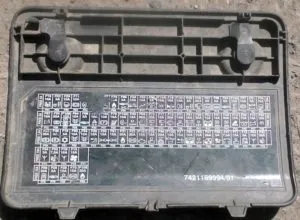
Fuse and relay box
The main fuse and relay box is located at the top of the instrument panel, on the passenger side behind a protective cover.
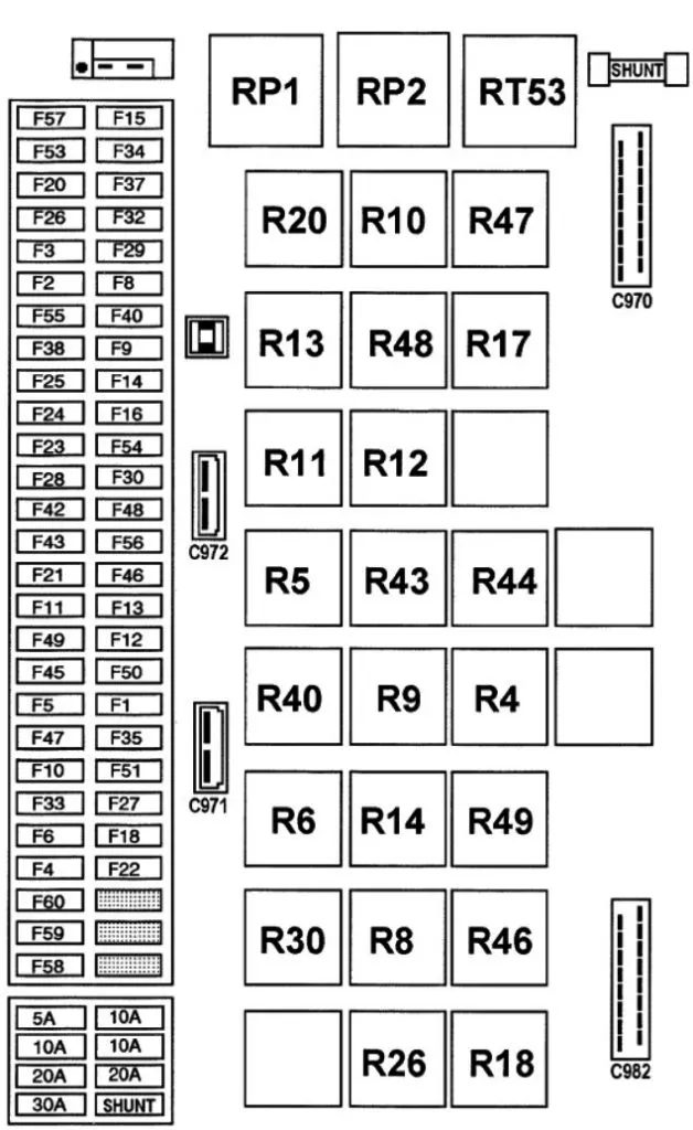
Option 1

| Trailer socket 7-pin “ABS/EBS” | F1 |
| Power supply for the SERVICE and DANGER indicator lights | F1 |
| control unit “ABS / ASR” | F1 |
| fuse for solenoid valves “ABS / ASR” (Front right / Rear left) | F1 |
| fuse for solenoid valves “ABS / ASR” (Front left / Rear right) | F1 |
| ABS emergency protection fuse | F1 |
| fuse for electric retarder disconnect unit | F1 |
| Parking lights right | F2 |
| Side lights right | F2 |
| Parking lights left | F3 |
| Left side lights | F3 |
| Power supply for trailer parking lights | F4 |
| Reserve +24 volts (for lighting) | F5 |
| Reserve +24 volts (for lighting) | F6 |
| Instrument cluster instrument lighting | F6 |
| Switch illumination | F6 |
| Fog light (or lights) | F8 |
| Fog lights | F9 |
| Low beam headlight right | F10 |
| Low beam headlight left | F11 |
| Left high beam headlight | F12 |
| Right high beam headlight | F13 |
| Long range floodlights | F14 |
| Windscreen wiper timing drive | F15 |
| Anti-theft device | F16 |
| Brake light switch under the brake pedal | F16 |
| Reversing lights | F16 |
| Emergency switch “TBV” (in RTMDR modification) | F16 |
| Instrument cluster indicator power supply circuit | F16 |
| heated exterior rear view mirrors | F16 |
| Air Conditioner Circuit | F18 |
| Roof vent motor | F20 |
| Backup power supply (after the main switch) | F21 |
| Autonomous heater “D1LCC” | F22 |
| Autonomous heater “D3LCC” (hair dryer) | F22 |
| Autonomous heater “Thermo 90” (wet) | F22 |
| Air Conditioner Circuit | F22 |
| Ventilation control device | F22 |
| footrest light fuse | F23 |
| Driver’s ceiling light | F23 |
| Sleeping area lampshade | F23 |
| Lower bunk lampshade | F23 |
| Ceiling lamp for the upper couch | F23 |
| Portable map reading lamp | F23 |
| Passenger window lift motor | F24 |
| Control tachograph clock | F25 |
| Sound alarm | F26 |
| Stop signal | F27 |
| control unit “ABS / ASR” | F28 |
| Swivel rear view mirror with defrost, left | F29 |
| Rotating rear view mirror with defrost, right | F29 |
| Controlling the orientation of the outside rearview mirror(s) | F29 |
| Power supply for additional elements of the control tachograph | F30 |
| Spotlight adjustment drives | F30 |
| cigarette lighter fuse | F30 |
| 12 volt converter (telecommunication circuit) radio | F30 |
| radio fuse | F30 |
| Windscreen wiper drive motor | F32 |
| windshield washer motor | F32 |
| headlight washer motor | F32 |
| socket fuse for diagnostics | F33 |
| Suspension control unit (6×2 / 6×4) | F33 |
| Direction indicator flasher | F34 |
| Power supply for car radio memory | F34 |
| Programmable switch (remote control) for an autonomous heater | F34 |
| Backup power (after contact of starter switch) | F35 |
| EBS control unit | F37 |
| Driver’s window lift motor | F38 |
| Backup power supply (after the main switch) | F40 |
| Matrix display | F42 |
| Control unit “TBV” | F42 |
| Working spotlight (tractor) | F43 |
| Valve illumination | F43 |
| Central locking control unit | F45 |
| Electric latch left | F45 |
| Electric latch right | F45 |
| Engine preheating switch | F46 |
| Time relay for central lubrication system | F46 |
| Matrix display | F46 |
| suspension computer (4×2) | F47 |
| suspension computer (6×2 / 6×4) | F47 |
| Remote control unit for suspension | F47 |
| Rear axle cushion pressure sensor (6×2) | F47 |
| Self-aligning axis time relay | F47 |
| VMAC computer | F48 |
| Exhaust Brake Solenoid Valves “J” | F49 |
| Fridge | F50 |
| Heated driver’s seat | F51 |
| Heated passenger seat | F51 |
| Step-down transformer (for 12 volt socket) | F51 |
| Socket for “SAE” | F51 |
| Backup power for video | F53 |
| Electric front sunblind | F54 |
| Electric side sunblinds | F54 |
| Backup power (after contact of starter switch) | F55 |
| Emergency switch “TBV” (in RTMDR modification | F56 |
| Control unit “TBV” | F56 |
| EBS control unit | F60 |
Fuse F30 is responsible for the cigarette lighter.
Fuses can be installed separately, outside the block:
- Cabin tilting pump – F84 40 A10
- Trailer socket 7-pin “ABS/EBS” – F85 20 A3
Decoding the relay
| Power relay after contact | RP1 |
| Power relay after contact | RP2 |
| Oil pressure relay | R4 |
| Parking light relay | R5 |
| Additional comfort elements relay | R6 |
| Lighting relay | R8 |
| Fog light relay | R9 |
| Fog light relay | R10 |
| Low beam headlight relay | R11 |
| High beam headlight relay | R12 |
| Long Range Floodlight Relay | R13 |
| Brake light relay | R14 |
| Backup relay | R17 |
| Electric retarder cut-off relay | R18 |
| Rear view mirror defrost relay | R20 |
| Brake pad relay | R26 |
| Exhaust Brake Relay “J” | R30 |
| Backup relay (for future connections) | R40 |
| Backup relay (for future connections) | R43 |
| Power supply relay of the control unit “VMAC” | R44 |
| Air Conditioning Compressor Relay | R46 |
| Backup relay | R47 |
| Backup relay | R48 |
| Air conditioning relay | R49 |
| Headlight Washer Timing Relay | RT53 |
| Starting relay | CE112 |
| Engine preheating relay | CE20 |
| Relay of electric valves “ABS / ASR” (Front left / Rear right) | R15 |
| Relay of electric valves “ABS / ASR” (Front right / Rear left) | R16 |
| ABS emergency protection relay | R19 |
| Self-aligning axle emergency shutdown relay | R21 |
| Engine stop relay (if the cabin overturns) | R23 |
| Cabin tilt relay | RP45 |
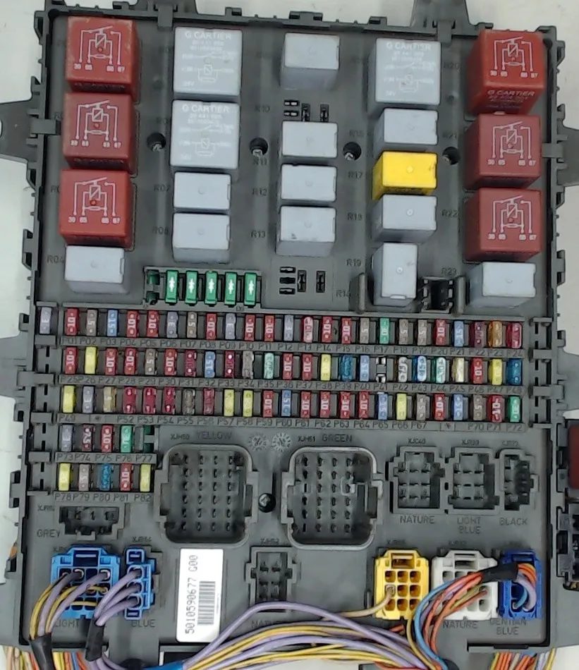
Option 2
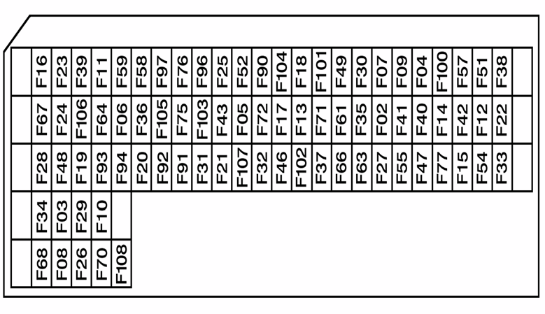
| Main information display | F03 7.5A |
| Safety and cabin tilt permission relay | |
| Cabin tilt motor power relay | |
| Main information display | F04 5A |
| Headlights of the washer pump motor | F05 30A |
| Main information display | F06 5A |
| Tachograph | |
| Vehicle control unit | F07 5A |
| Main information display | F08 5A |
| Engine immobilizer ECU | |
| Alarm ECU | |
| Doors central lock ECU | |
| Air production control unit | |
| Bodybuilder by prior arrangement with ECU management | F09 5A |
| Air conditioning control unit | F10 30A |
| Hydraulic retarder ECU | F11 10A |
| Electric retarder ECU | |
| Gear Shift ECU | F12 15A |
| Automatic transmission control unit | |
| Lighting and signaling control ECU | F13 20A |
| Windscreen wiper motor delay time relay | |
| Windscreen washer pump motor | |
| Windscreen wipers drive motor | |
| Cigarette lighter | F14 15A |
| Car diagnostic socket | F15 5A |
| Vehicle Data Extraction Connector | |
| Selection control | F16 10A |
| Interwheel differential lock indicator light | |
| Rear wheel lock solenoid valve | |
| Power take-off mechanism engagement solenoid valve No. 1 | |
| PTO engagement solenoid valve No. 2 | |
| PTO engagement solenoid valve No. 3 | |
| Center differential lock solenoid valve | |
| High beam headlight | F17 10A |
| Electric horn | F18 10A |
| Air horn | |
| Air conditioning control unit | F19 5A |
| Radio | F20 10A |
| Alarm ECU | |
| Doors central lock ECU | |
| ABS/EBS end connector | F21 20A |
| One overhead light on the driver’s side | F22 10A |
| Single upper lamp on the front passenger side | |
| Right top light (door) | |
| Driver’s reading light | |
| Front passenger reading light | |
| Overhead lighting for the lower bunk | |
| Left top light (door) | |
| Left top light (atmosphere) | |
| Right top light (ambience) | |
| Overhead Double Tier Overhead Lighting | |
| Driver side lighting | |
| Stepped front passenger lighting | |
| Steering axle lock angle sensor | F23 5A |
| Steering axle lock angle sensor | |
| Air suspension control unit | |
| Steering axle ECU | |
| Fuel Heater Resistor #2 | F24 20A |
| Available power source (equipment in the road warning pictogram) | F25 10A |
| Available power source (lighting) | |
| Equipment in unlocked position signal lamp | |
| Equipment light information signal light | |
| 15-pin trailer connector | |
| Available power source (after ignition) | F26 15A |
| Electric motor for driver’s door window lift | F27 20A |
| Electric motor for the front passenger door glass lifter | |
| EBS brake control system | F28 20A |
| Automatic transmission selector | F29 10A |
| On-board ECU control interface | |
| Lighting and signaling control ECU | F30 30A |
| ECU for cabin temperature control system | F31 20A |
| Alarm ECU | |
| Air/water additional heater | |
| Air/Air Additional Heater | |
| Air conditioning control unit | |
| Available power supply (after main switch) | F32 10A |
| Cabin tilt motor | F33 30A |
| On-board ECU control interface | F34 3A |
| Lighting and signaling control ECU | F36 10A |
| Voltage converter (24V/12V – 15A) for audio communication system | F37 10A |
| Radio | |
| Additional signal lights signal lamp | F38 10A |
| Working spotlight | |
| Vehicle control unit | F39 15A |
| Left rear view mirror defrost resistor | |
| Right rear view mirror defrost resistor | |
| Heated and rotating rear view mirror power relay | |
| Windshield Defrost Control Relay | |
| Engine control unit | F40 30A |
| Starter | |
| Starting relay | |
| Air heater relay | |
| Engine brake no. 1 electromagnetic valve | |
| Exhaust brake solenoid valve | |
| Changing the range of the solenoid valve | |
| Electric splitter control valve | |
| Engine cooling fan speed control solenoid valve | |
| Starter | F41 15A |
| Starting relay | |
| Engine brake no. 1 electromagnetic valve | |
| Engine brake no. 2 electromagnetic valve | |
| Exhaust brake solenoid valve | |
| Changing the range of the solenoid valve | |
| Electric splitter control valve | |
| Air heater relay | F42 10A |
| Engine cooling fan speed control solenoid valve | |
| 24V socket | F43 15A |
| Automatic transmission diagnostic socket | |
| Rotating Lighthouse No. 1 | F46 15A |
| Rotating Lighthouse #2 | |
| Beacon power supply relay | |
| Air production control unit | F47 7.5A |
| Brake Hold On Control | F48 3A |
| EBS brake control system | |
| Air suspension control unit | F49 5A |
| Vehicle Power Delivery (ADR) Control Unit | |
| Steering axle ECU | F51 5A |
| Automatic transmission selector | F52 10A |
| Engine immobilizer ECU | |
| Cabin emergency stop control | |
| Vehicle control unit | |
| After the ignition is turned on, power relay No. 1 | |
| After the ignition is turned on, power relay No. 2 | |
| After turning on the ignition, power relay No. 3 | |
| Accessory Power Relay #1 | |
| Accessory Power Relay #2 | |
| Generator Circuit Ground Relay (ADR) | |
| Generator chain tension resistance | |
| Car diagnostic socket | |
| On-board control unit | F54 10A |
| Hydraulic retarder ECU | F57 10A |
| Cabin emergency stop control | F58 3A |
| Generator Circuit Ground Relay (ADR) | |
| Preliminary preparation for on-board control unit (ECU) | F59 10A |
| Brake Hold On Control | |
| Reverse Light Relay | |
| Voltage converter (24V/12V) for IT package | F61 15A |
| 24V socket | F63 15A |
| 15-pin trailer connector | F64 10A |
| Instrument Lighting | F66 10A |
| Front Lighting Grille | |
| Roof ventilation motor | |
| Gear Shift ECU | F67 10A |
| Automatic transmission control unit | |
| Voltage converter (24V/12V – 10A) for audio communication system | F68 20A |
| Voltage converter (24V/12V – 15A) for audio communication system | |
| Voltage converter (24V / 12V) – 12 and 24 Volt built-in sockets | |
| Refrigerator compartment | |
| Fridge | |
| Additional 24V socket | |
| ABS/EBS end connector | F70 10A |
| Available power source (after ignition) | F71 15A |
| High beam headlights high beam | F72 10A |
| Low beam headlight | |
| Available power source (generator information, engine running) | F75 15A |
| Right heated seat | |
| Left heated seat | |
| Car service | F76 10A |
| Air/Air Additional Heater | |
| Generator Circuit Ground Relay (ADR) | |
| Additional air/water heater solenoid valve | |
| Available power supply (after main switch) | F77 15A |
| Lighting and signaling control | F90 3A |
| Rear fog light power relay | |
| High beam headlight relay | |
| Fog Light Power Relay | |
| Night Light Relay Switches | |
| Relay for turning off fog lights when high beam headlights are on | |
| Clearance lantern No. 1 | F91 10A |
| Clearance light no. 2 | |
| Left front side / side lights | |
| Right side light No. 3 | |
| Right side lights No. 4 | |
| Right rear side / side lights | |
| Left side roof / side lights | |
| Anti-glare overhead left side lights | |
| Vehicle Power Delivery (ADR) Control Unit | |
| Right front side / side lights | F92 10A |
| Left side lights No. 1 | |
| Side lights LG No. 2 | |
| Side lights LG No. 3 | |
| Side lights LG No. 4 | |
| Left rear side / side lights | |
| Left side roof / side lights | |
| Glossy right side lights with anti-glare coating | |
| Available Power Source (Right Rear Parking Light(s)) | F93 10A |
| 15-pin trailer connector | |
| Available Power Source (Left Rear Parking Light(s)) | F94 10A |
| 15-pin trailer connector | |
| Night lighting instruments and controls | F96 3A |
| Available power source (night lighting) | F97 5A |
| High beam headlights high beam | F100 15A |
| Fog lights | |
| High beam headlight | |
| Low beam headlight | |
| Left fog light | |
| Right fog lights | |
| Fog lights | F101 10A |
| Rear fog light | |
| Rear fog light | |
| 15-pin trailer connector | |
| Main information display | F102 10A |
| Right high beam high beam | |
| Left high beam high beam | |
| Available power source (feedback) | F103 10A |
| Reversible braking control | |
| Reversing lights | |
| Reversing lights | |
| Outer horn | |
| 15-pin trailer connector | |
| Left brake lights | F104 10A |
| Right brake lights | |
| 15-pin trailer connector | |
| Nitrogen oxide gas concentration sensor | F107 10A |
| AdBlue Feed Control Pump Module | |
| Engine water circuit bypass solenoid valve | |
| Air / additional heater | F108 20A |
Fuse number 14 for 15A is responsible for the cigarette lighter.
Relay designation
| After the ignition is turned on, power relay No. 1 | R01 |
| After the ignition is turned on, power relay No. 2 | R02 |
| After turning on the ignition, power relay No. 3 | R03 |
| Heated and rotating rear view mirror power relay | R04 |
| Generator controlled power relay (engine running) | R05 |
| Right and left side relay / side and parking light power relay | R06 |
| Night Light Relay Switches | R07 |
| High beam headlight relay | R08 |
| Generator Circuit Ground Relay (ADR) | R09 |
| Additional heater power relay | R10 |
| Safety and cabin tilt permission relay | R11 |
| Right and left side relay / side light and side light power supply relay (trailer and bodywork) | R12 |
| Brake light power relay | R13 |
| High beam high beam relay | R14 |
| Windscreen wiper motor delay time relay | R15 |
| Automatic transmission ECU power supply relay | R16 |
| Starting relay | R17 |
| Rear fog light power relay | R18 |
| Air Suspension Power Relay | R19 |
| Power supply relay for vehicle and engine ECU | R20 |
| Accessory Power Relay #1 | R21 |
| Accessory Power Relay #2 | R22 |
| Fog Light Power Relay | R23 |
Some models have additional high-power fuses on the battery cover.