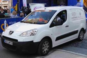
Peugeot Partner is a compact van, designed on the basis of a passenger car, produced since 1996. The first generation was delivered to the market in 1997, 1998, 1999, 2000, 2001, 2002, 2003, 2004, 2005, 2006 and 2007. During this time, it received 2 restylings. After a complete update, the 2nd generation was produced in 2008, 2009, 2010, 2011, 2012, 2013, 2014, 2015, 2016, 2017, 2018 and to the present day in various modifications ( tepee, with an extended and standard base, etc.). We offer for review information on the diagrams of all fuse boxes and relays of the Peugeot Partner Tepee with a detailed description of the elements for all generations, we will show the fuse responsible for the cigarette lighter and the operating manual.
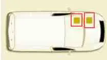
In this model there are 2 main places with the location of the fuse boxes :
- on the left under the dashboard (under the cover)
- in the engine compartment (near the battery under the protective cover).
1st generation
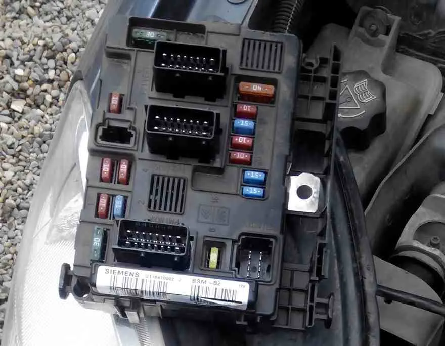
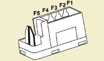
Block under the hood
Block location
Real photo of the block
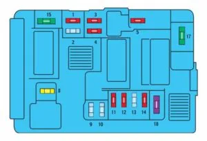
| No. | Chain of protection | |
| 1 | 10 A | Reversing light, preheating unit, clutch release contact |
| 2 | 15 A | Gasoline pump |
| 3 | 10 A | Electronic control unit (ECU) of the ABS system |
| 4 | 10 A | Engine ECU |
| 5 | 10 A | Spare |
| 6 | 15 A | Front fog lights |
| 7 | 20 A | Headlight washer |
| 8 | 20 A | Engine ECU, Electric Fan Relay |
| 9 | 15 A | Left low beam lamp |
| 10 | 15 A | Right low beam lamp |
| 11 | 10 A | Left high beam lamp |
| 12 | 10 A | Right high beam lamp |
| 13 | 15 A | Sound signal |
| 14 | 10 A | Windscreen washer |
| 15 | 30 A | Engine sensors |
| 16 | 30 A | Air pump |
| 17 | 30 A | Windscreen wiper |
| 18 | 40 A | Electric fan of the climate control system |
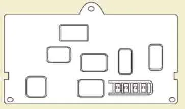
Block in the cabin
Scheme
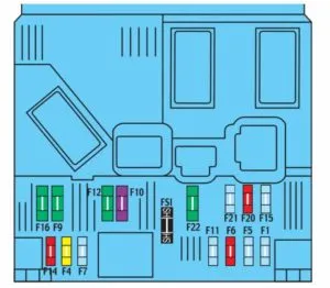
Table with decoding
| No. | Chain of protection |
| F1 | 15A Rear Window Wiper (with hinged doors), 12V Socket (Modutop) |
| F4 | 20A Car radio instrument cluster, display, COM2000 |
| F5 | 15A Security Alarm Siren |
| F6 | 10A Diagnostic connector Citroen Berlingo |
| F7 | 15A Security alarm |
| F9 | 30A Seat heating system, electric fan Modutop |
| F10 | 40A Rear window heating element, heated outside rear view mirrors |
| F11 | 15A Rear Window Wiper |
| F12 | 30A Electric sunroof, electric windows Citroen Berlingo |
| F14 | 10A Network VAN COM2000 |
| F15 | 15A VAN Network Instrument Cluster, Car Radio, Display |
| F16 | 30A Electric Door Locks |
| F20 | 10A Rear right brake light |
| F21 | 15A Rear left brake light |
| F22 | 20A Citroen Berlingo cigarette lighter fuse, 12V socket, electric outside rearview mirrors, interior lights, map and document reading light |
Fuses No. 1 and 22 are responsible for the cigarette lighter.
2nd generation
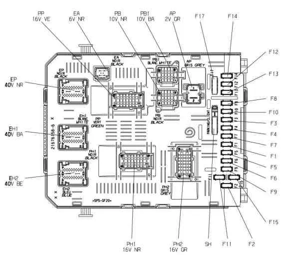
Blocks under the hood
Main fuse and relay box
Designation
Fuses
- F1 20A Engine Management Computer – Power Supply to the Electric Control Unit of the Two-Speed Electric Fan Group
- F2 15A sound alarm
- F3 10A Front and rear windscreen washers
- F4 20A Headlight washers
- F5 15A + battery Fuel heating system DV6 – fuel pump TU5JP4
- F6 10A + after contact ABS/ESP computer and dual relay – steering wheel angle sensor – gyrometer stability control system acceleration meter – power steering pump mechanism
- F7 10A brake contact sensor – clutch pedal limit switch
- F8 25A starter winding
- F9 10A after contact protection blocking module 3 relay – headlight range corrector motor
- F10 30A ignition coil control TU5JP4 – injector control TU5JP4 – power supply for the electromagnetic valve of the injection pump DV6
- F11 40A blower fan relay on
- F12 30A Front wiper low and high speed control
- F13 40A after contact power supply SM (intelligent service module)
- F14 30A Exhaust Gas Temperature Recovery Pump Control
- F15 10A Right High Beam Headlight
- F16 10A Left High Beam Headlight
- F17 15A left low beam headlight
- F18 15A Right low beam headlight
- F19 15A Tank cleaning solenoid valve TU5JP4 – oxygen sensors at the inlet and outlet TU5JP4 – turbocharged air heating solenoid valve 1-2 DV6
- F20 10A Fuel Liquid Sensor DV6 Turbocharger Pressure Regulating Solenoid Valve DV6 Exhaust Temperature Regulating Solenoid Valve
F21 5A Air Flow Meter DV6 Power Supply to Electric Fan Control Unit 2-Speed Maxi Fuse Module (PSF1)
Relay
- R1 main relay engine control computer
- R2 relay of the power circuit of the engine control computer
- R3 air supply system relay
- R4 windshield wiper relay
- R5 Front wiper low speed relay – Front wiper high speed relay
- R6 distributor relay + after contact
- R7 air conditioning fan relay
- R8 starter relay
- R9 Front Windscreen Washer Relay
- R10 rear window washer relay
- R11 headlight washer relay
- R12 horn relay
Block on the battery cover
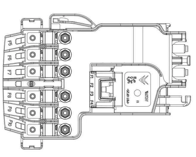
- Charging Status Module – 5A
- Diagnostic connector – 15A
- Brake pedal switch resistance – 15A
- –
- Power supply for the power steering pump group – 80A
- Pre-Post Heater Control Module – 70A
- Protection blocking module 3 relays – 100A
- –
- –
- Simple motor protection relay – 30A
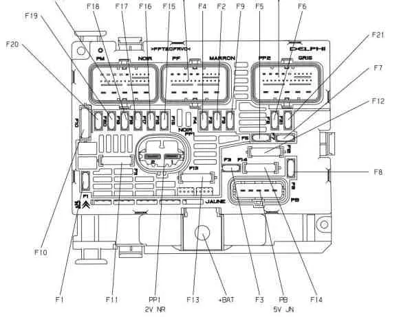
Blocks in the cabin
Main blocks under the panel on the left
General scheme
Description of fuses
- 15A – Rear window wiper
- –
- 5A – Airbag
- 10A – Air conditioning, diagnostic connector, rear view mirror, headlight adjuster
- 30A – Window lifters
- 30A – Locks
- 5A – Rear courtesy light, front courtesy light, sunroof
- 20A – Car radio, CD changer, display, tire pressure monitoring unit, security alarm and siren
- 30A – 12V sockets front and rear
- 15A – Upper part of the steering column
- 15A – Ignition switch low current circuit
- 15A – Rain and light sensor, airbag
- 5A – Instrument panel
- 15A – Parking sensors, air conditioning control panel, hands-free system
- 30A – Power supply for the locking system
- –
- 40A – Heated rear window and mirrors
Fuse number 9 is responsible for the cigarette lighter.
Description of the relay
- R1 – Front impulse window lifter relay
- R2 – Rear window wiper relay
- R3 – Accessories relay + ACC
- R4 – Door lock relay
- R5 – Rear door super lock relay
- R6 – Front door super lock relay
- R7 – Computer wake-up relay
- R8 – Heated rear window relay
Block 2 diagram
- –
- 20A – Seat heating
- –
- 15A – Relay for folding rear view mirrors
- 15A – Relay socket for connecting the refrigeration chamber
Additional block
If the vehicle is equipped with the appropriate systems, an additional fuse box is installed for the towing device and trailer, as well as other body modifications and platforms with a cabin. It is located behind the restrictive partition on the right.
General scheme
Located here:
- 15A – Ignition switch relay, optional generator
- 15A – Trailer power supply 12V
- 15A – Transformer DC power supply circuit
- 40A – Emergency lights