Opel Vectra C (opel vectra s) is the third generation of the Opel Vectra model range. Vectra C was produced in 2002, 2003, 2004, 2005, 2006, 2007, 2008. On its basis, the luxury model Opel Signum was later built. In this publication, you will find a description of the fuse boxes and relays Opel Vectra C, with block diagrams and photographs. Let’s highlight the fuse responsible for the cigarette lighter.

The design of the units and the purpose of the elements in your Opel Vectra C may differ and depend on the year of manufacture, the level of electrical equipment and the country of delivery.
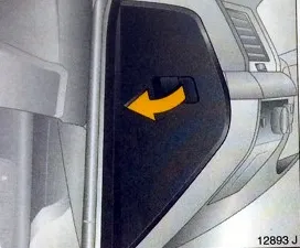
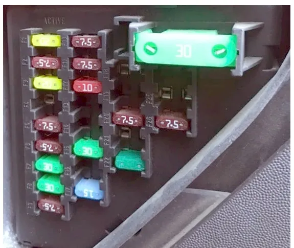
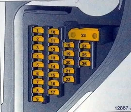
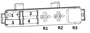
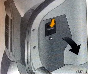
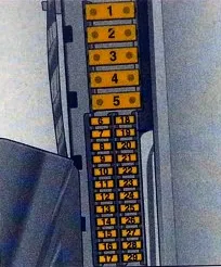
Block in the cabin
It is located on the left end of the dashboard, on the driver’s side, and is covered by a protective cover.
| 1 | 20A Audio system, additional heater, DVD player |
| 2 | 7.5A Air Conditioner – Manual Temperature Control, Air Conditioner/Heater Fan Motor |
| 3 | 20A Luke |
| 4 | Reserve |
| 5 | 7.5A Door electrical control unit |
| 6 | 7.5A Brake lights |
| 7 | 30A Multifunctional Control Unit 1 |
| 8 | 30A Door Electrical Control Unit |
| 9 | 7.5A Multifunctional Control Unit 1 |
| 10 | 7.5A Steering Column Electrical Control Unit |
| 11 | 7.5A Diagnostic Link Connector (DLC) |
| 12 | 15A Battery Overload Protection |
| 13 | Reserve |
| 14 | Reserve |
| 15 | 30A Driver’s door electrical equipment control unit |
| 16 | Reserve |
| 17 | 15A Instrument cluster, multi-function display |
| 18 | 7.5A Ignition switch, air conditioning |
| 19 | Reserve |
| 20 | 7.5A Lateral Movement Sensor |
| 21 | 7.5A Telematics |
| 22 | 30A Cigarette Lighter |
| 23 | 30A Air Conditioner – Manual Temperature Control, Air Conditioner/Heater Fan Motor |
| 24 | Reserve |
| 25 | 7.5A Air Conditioner – Manual Temperature Control, Air Conditioner/Heater Fan Motor |
| 26 | 7.5A Multi-function display, instrument cluster |
Fuse number 22 for 30A is responsible for the operation of the cigarette lighter.
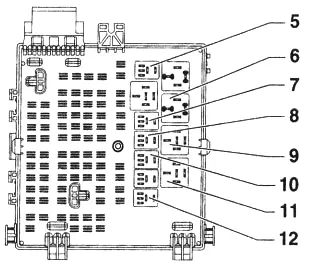
There may be some relays located on the back side of the block.
Scheme
- Main Ignition Circuit Relay (Terminal 15a)
- Relay terminal 15
- Interior ventilation relay
- Heater Fan Motor Relay
Blocks under the hood
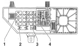
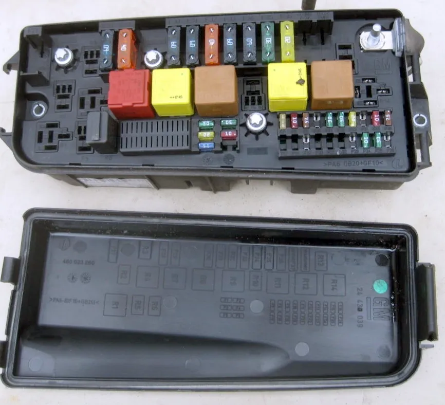
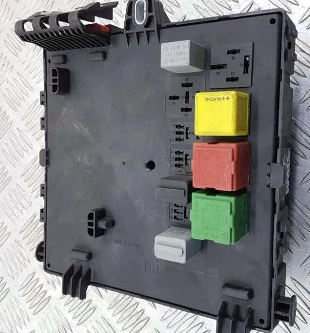
Main block
It is located next to the battery and the side stand, covered with a protective cover, on the back of which the current diagram will be applied.
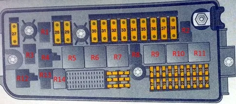
| R1 | |
| R2 | |
| R3 | |
| R4 | |
| R5 | Engine Management System Relay |
| R6 | Starter relay |
| R7 | Windshield Wiper Motor Relay (ON/OFF) |
| R8 | |
| R9 | Main Ignition Circuit Relay |
| R10 | Windshield Wiper Motor Relay (Low/High Wiper Speed) |
| R11 | Headlight washer relay |
| R12 | |
| R13 | |
| R14 | Air conditioning compressor electromagnetic clutch relay |
| 1 | 20A Electronic Engine Control Unit |
| 2 | 25A Starter |
| 3 | 20A Sound signal |
| 4 | 10A Air conditioning – climate control |
| 5 | 15A Windscreen wiper/washer |
| 6 | Reserve |
| 7 | 15A ESP (Electronic Stability Program) control unit |
| 8 | 10A Headlights, Windshield Washer Nozzle Heaters |
| 9 | 7.5A Power Steering |
| 10 | 10A Headlight Correction Control Unit |
| 11 | 30A Windscreen Wiper |
| 12 | 30A Windscreen Wiper |
| 13 | 7.5A ESP (Electronic Stability Program) control unit |
| 14 | 10A Motor Control |
| 15 | 10A Electronic Engine Control Unit |
| 16 | 7.5A Anti-lock Braking System (ABS) |
| 17 | Reserve |
| 18 | Reserve |
| 19 | 5/10/15A Headlight range control unit, headlight range control, xenon headlights |
| 20 | 5A Headlight Corrector |
| 21 | Reserve |
| 22 | Reserve |
| 23 | 20A Additional heater |
| 24 | 30A Battery Voltage |
| 25 | 30A Battery Voltage |
| 26 | Reserve |
| 27 | Reserve |
| 28 | 60A Control unit for opening/closing drive of trunk lid (rear door) |
| 29 | 40A Anti-lock Brake System (ABS) |
| 30 | 60A Control unit for opening/closing drive of trunk lid (rear door) |
| 31 | 60A Fuse/Relay Box Instrument Panel |
| 32 | 40A Anti-lock Brake System (ABS) |
| 33 | 60A Main Ignition Relay, Fuse/Relay Box, Instrument Panel |
| 34 | 60A Control unit for opening/closing drive of trunk lid (rear door) |
| 35 | 30A/40A Cooling Fan Motor |
| 36 | 20A/30A Cooling Fan Motor |
| 37 | Adaptive Headlight System – AFL |
| 38 | Reserve |
Additional block
Can be placed next to the main one.
Scheme
Purpose
Option 1
- –
- 60A Glow Plug Control Unit
- 30A Fuel Filter Heater Relay
- 60A Glow Plug Control Unit
R3 – Fuel filter heater relay
Option 2
R2, R3 – Fuel heater relay
- –
- 30A Starter
- –
- 20A Sound signal
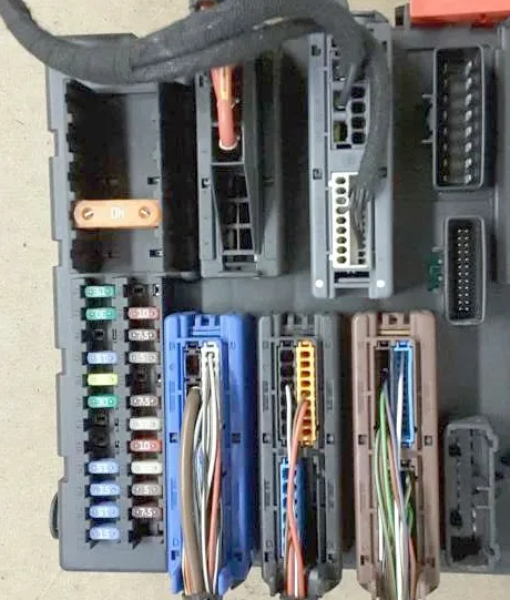
Block in the trunk
This unit is located in the luggage compartment on the left, in the glove compartment.
| 1 | Reserve |
| 2 | Reserve |
| 3 | 40A Electric Seat |
| 4 | 40A Rear Window Defogger |
| 5 | 40A Electric Seat |
| 6 | 30A Electric window lifter – right rear |
| 7 | 30A Electric window lifter – left rear |
| 8 | 15A Seat heater, rear right |
| 9 | 15A Anti-theft system, horn |
| 10 | 20A Fuel Pump |
| 11 | 25A Battery Voltage |
| 12 | 12A Seat heating – rear left |
| 13 | 20A Trailer Electrical Socket |
| 14 | 15A Rear Window Wiper |
| 15 | 15A Seat heater, seat ventilation system, front left |
| 16 | 15A Seat heater, rear right |
| 17 | 15A Additional equipment connection socket |
| 18 | 30A Boot lid/rear door lock |
| 19 | 10A Battery Voltage |
| 20 | 7.5A Central locking |
| 21 | 5A Volume change sensor (anti-theft system) |
| 22 | 30A Remote control trunk lock |
| 23 | 7.5A Anti-Theft Glass Wire (Anti-Theft Glass Break Sensor) |
| 24 | 25A Battery Voltage |
| 25 | 10A Suspension Control System |
| 26 | 25A Ignition Switch |
| 27 | 5A Seat occupant sensor, tire pressure monitoring system, rain sensor, air conditioning system |
| 28 | 7.5A Parking Sensors |
| 29 | Reserve |
Some relay elements can be attached to the back side of the block.
Purpose of the relay
| 5 | Rear window cleaner |
| 6 | Terminal 15 |
| 7 | Rear left seat heating |
| 8 | Rear right seat heating |
| 9 | Rear window heating |
| 10 | Sound signal/anti-theft alarm |
| 11 | Fuel pump |
| 12 | Single lock/fuel filler flap |