Mitsubishi Pajero Sport 1st generation was designed on the basis of Mitsubishi L200 and was produced in 1996, 1997, 1998, 1999, 2000, 2001, 2002, 2003, 2004, 2008, 2002 During this time the model underwent restyling and minor updates. In this publication you can find a description of the fuses and relays of Mitsubishi Pajero Sport 1 with block diagrams, photo examples of execution and their locations. We will show the fuse responsible for the cigarette lighter.

The number of elements in the blocks may differ from those shown and depends on the year of manufacture, equipment level and region of delivery. Check the assignment with your diagrams on the block cover.
Blocks in the cabin
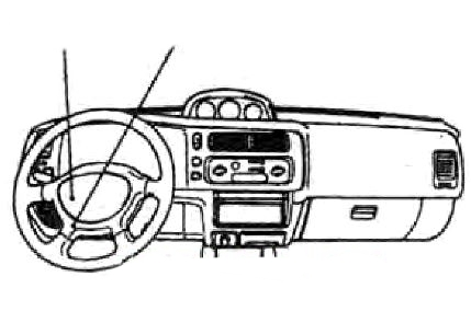
Under the dashboard, on the driver’s side, there are 2 blocks: a fuse block and a relay block.
Fuse block
Photo – example
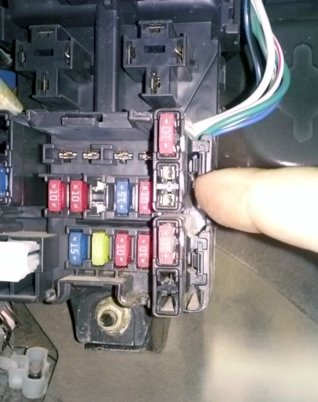

Description
| 1 | 10A Turn signals |
| 2 | 10A Audio system |
| 3 | 15A Central door locking |
| 4 | 10A Air conditioning unit electric fan relay |
| 5 | 15A Cigarette lighter |
| 6 | 20A Windshield wiper |
| 7 | 10A Reversing lights |
| 8 | 10A Instrument cluster |
| 9 | 10A Stop signals |
| 10 | 10A Audible signals |
| 11 | 10A Power windows |
| 12 | 10A automatic transmission |
| 13 | 15A high pressure fuel pump |
| 14 | 15A Sunroof drive |
Fuse number 5 at 15A is responsible for the cigarette lighter.
Some relay elements may be attached to the correct part of the block.
Scheme
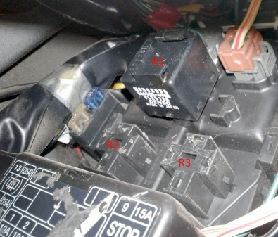
- R1 – turn signal relay
- R2 – rear window and side mirror heating relay
- R3 – heater fan motor relay (for L200)
Relay block
Scheme

Transcript
- Ignition switch (lock) wiring harness;
- Relay socket for connecting additional equipment;
- Rear heater motor relay;
- Power window relay;
- Fuse (30 A) for the rear door window heater;
- Fuse (15 A) for the rear heater;
- Relay-timer for the rear door window heater and exterior mirrors;
- Tailgate window wiper relay-interrupter;
- Fuse (15 A) for sockets for connecting additional equipment;
- Fuse (10 A) for heated exterior mirrors.
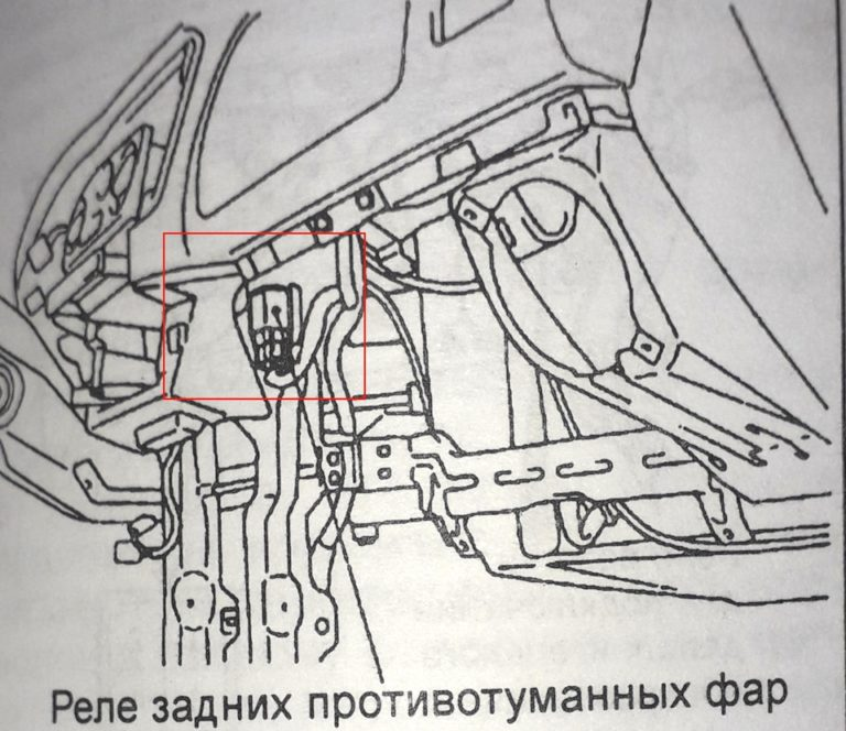
Depending on the year of manufacture and equipment level, it is possible to place individual additional relays and other control units outside the presented units, for example, a fuel pump control unit.
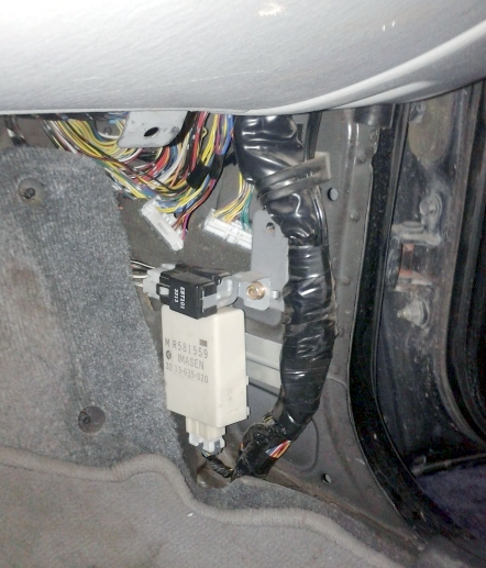
Or the rear fog light relay.
Blocks under the hood
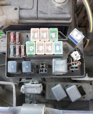
Main unit
Located on the left side of the engine compartment, next to the battery.
Example of a circuit from the block cover
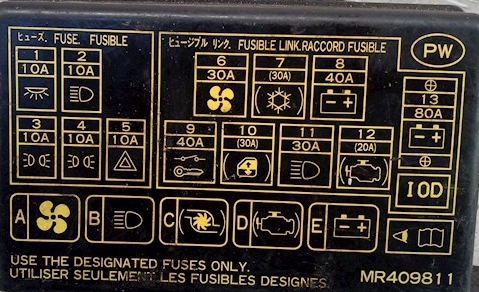
Scheme
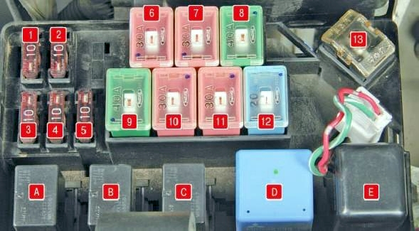
Marking
| 1 | 10A Interior lighting |
| 2 | 10A High beam |
| 3 | 10A Rear parking lights |
| 4 | 10A Rear parking lights |
| 5 | 10A Emergency alarm |
| 6 | 30A Electric fan of the air conditioning unit |
| 7 | 30A Air conditioner |
| 8 | 40A Starting system |
| 9 | 40A Ignition switch (lock) |
| 10 | 30A Glass lifts |
| 11 | 30A Low beam |
| 12 | 20A Engine control system |
| 13 | 80A Generator |
| A | Air conditioning unit electric fan relay |
| B | Headlight relay |
| C | Fog light relay |
| D | Starter relay |
| AND | Starting system relay |
Battery unit
Located on the positive terminal of the battery.
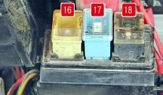
Appointment
- 16 – 60A Anti-lock braking system (ABS)
- 17 – 20A Fog lights
- 18 – 80A Glow plugs
Additional elements
An additional unit is attached next to the main unit.
Scheme
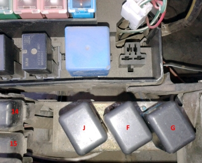
Description
- 14 – 25A Condenser fan
- 15 – 10A Air conditioner compressor
- J – reserve
- F – Air conditioning compressor relay
- G – Electric condenser fan relay
It is also possible to install some relays on the right side of the engine compartment.
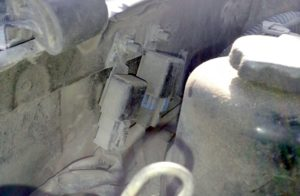
Appointment
- relay signal
- ABS relay