Mitsubishi Pajero Sport 3rd generation was produced in 2016, 2017, 2018, 2019, 2020, 2021. In this publication you will find a description of the fuses and relays of the Mitsubishi Pajero Sport 3rd generation with block diagrams and photos – examples of execution. We note the cigarette lighter fuse.

Check the purpose of the elements with your diagrams. Depending on the level of equipment, there may be a difference in the presented material and your execution of the blocks.
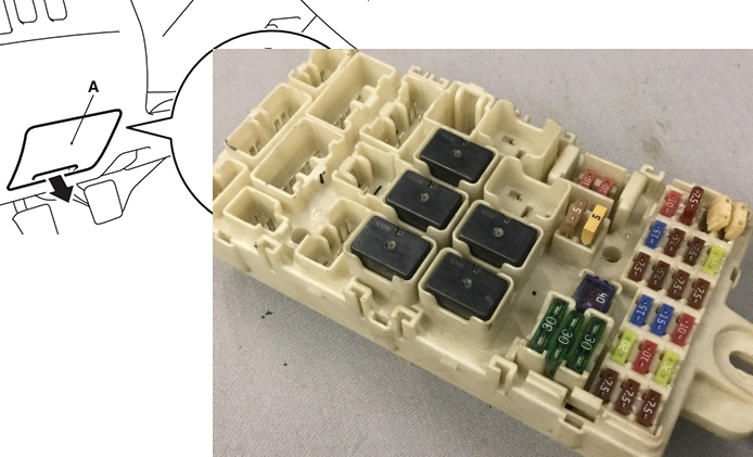
Cabin block
Located at the bottom of the instrument panel on the driver’s side behind a protective cover.
Block location
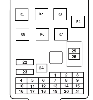
Fuse description
| 1 | 7.5A Side lights (left) |
| 2 | 15A Cigarette lighter |
| 3 | 10A Ignition coil |
| 4 | 7.5A Starter |
| 5 | 20A Roof hatch |
| 6 | 15A Socket, Accessory Connector |
| 7 | 7.5A Side marker lights (right), air conditioning ECU, ASC OFF switch, blind spot warning switch, combined meter, driving mode switch, electric parking brake switch |
| 8 | 7.5A Exterior mirrors |
| 9 | 7.5A engine ECU and fuel pump relay |
| 10 | 7.5A Control unit |
| 11 | 10A Rear fog light |
| 12 | 15A Central locking, Diagnostic connector |
| 13 | 10A Air conditioning ECU, camera ECU, central interior lamp, column switch, instrument cluster, door light lamp, electric parking brake switch, front interior lamp, internet interface control unit, key reminder switch (ILL), KOS and OSS ECUs, lighting control sensor, luggage compartment light lamp, multi-display, radio/CD player and rear display |
| 14 | 15A Rear window wiper glass |
| 15 | 7.5A Instrument panel, blind spot warning sensor, high beam warning control unit, steering column switch |
| 16 | 7.5A A/C compressor relay, A/C condenser fan relay, fan relay, heater controller, rear fan relay, rear cooler control panel, rear fan switch and rear window defroster relay |
| 17 | 20A Seat heating |
| 18 | 10A Accessory Power, Heater Controller Assembly |
| 19 | 7.5A Heated exterior mirrors |
| 20 | 20A Janitors |
| 21 | 7.5A Reversing lights, ATC control unit, ETACS control unit, multifunction display, radio/CD player, rear combination lamp (rear), rearview mirror assembly and SRS control unit |
| 22 | 30A Rear window heater, Fuse No. 19, glass antenna choke coil and rear window heater |
| 23 | 30A Heater fan motor relay |
| 24 | 40A Power seats |
| 25 | 10A Audio system, Accessory socket relay, ETACS-ECU, multi-display, radio/CD player and rear display |
| 26 | 15A Fuse No. 13 and ETACS-ECU |
Fuses numbered 2 and 6, as well as relay numbered 2, are responsible for the operation of the cigarette lighter and power outlets.
Relay designation
- R1 – Seat heating relay
- R2 – Auxiliary equipment socket power relay
- R3 – Rear fog light relay
- R4 – Fuel pump relay
- R5 – Fan relay
- R6 – Rear window heating relay
- R7 – Reserve
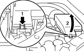
Block under the hood
Located in the left side of the engine compartment, near the battery.
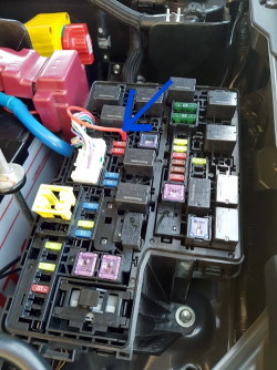
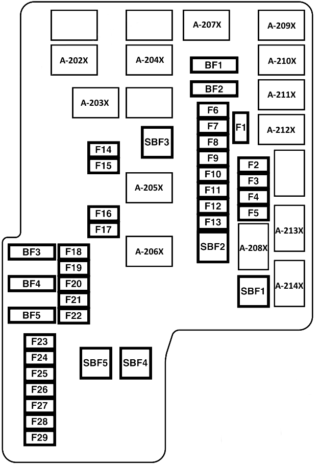
Purpose of fuses
| SBF1 | 40A Fuse No. F5, ACC relay circuit, ETACS – ECU (taillight relay circuit), IG1 relay circuit, IG2 relay circuit, ignition switch circuit and starter |
| SBF2 | 30A Main switch for electric window lifter and electric window lifter motor |
| SBF3 | 40A Power seat (front passenger side) |
| SBF4 | 30A ABS – ECU and ASTC – ECU |
| SBF5 | 30A Electric parking brake |
| BF1 | 30A Audio Amplifier |
| BF2 | 40A Rear fan motor |
| BF3 | Reserve |
| BF4 | Reserve |
| BF5 | Reserve |
| F1 | Reserve |
| F2 | 20A Air flow sensor <6B3, 4N1>, camshaft position sensor <6B3>, crankshaft angle sensor <6B3>, EGR cooler bypass control solenoid valve <4N1>, engine ECU, EGR valve <6B3>, glow control unit <4N1>, glow plug relay <4D5>, injector <6B3>, oil feed control valve <6B3, 4N1>, oxygen sensor, purge control solenoid valve <4N1>, throttle servo relay <4N1> and variable geometry control solenoid valve <4N1> |
| F3 | 15A Fuel pump and sensor assembly <6B3> |
| F4 | Reserve |
| F5 | 7.5A Engine ECU <6B3> |
| F6 | 15A Engine ECU <6B3> |
| F7 | 20A Air conditioning compressor and clutch assembly |
| F8 | 20A Automatic transmission control unit |
| F9 | 10A Daytime running lights, daytime running light relay and headlight assembly (DRL) |
| F10 | 7.5A Generator |
| F11 | 7.5A Engine – ECU |
| F12 | 10A Electric steering lock, engine switch and KOS & OSS-ECU |
| F13 | 15A Front fog light relay and front fog light relay |
| F14 | 10A Headlight assembly (HI: LH) |
| F15 | 10A Headlight assembly (HI: RH) and spare connector (for trailer) |
| F16 | 15A Headlight assembly and manual headlight range adjustment switch |
| F17 | 15A Headlight assembly (right) |
| F18 | 15A Heated steering wheel ECU |
| F19 | 15A ETACS-ECU (FET turn signal lamp) |
| F20 | Reserve |
| F21 | 20A Air conditioner condenser fan motor |
| F22 | 15A Stop signal relay |
| F23 | 20A Transfer – EBU |
| F24 | 20A Seat heating control unit |
| F25 | 20A Headlight washer motor and headlight washer relay |
| F26 | Reserve |
| F27 | 10A Horn and horn relay |
| F28 | Reserve |
| F29 | Reserve |
Relay decoding
| A-202X | Air conditioner condenser fan relay |
| A-203X | Headlight Washer Relay |
| A-204X | Horn relay |
| A-205X | Headlight Relay (HI) |
| A-206X | Headlight Relay (LO) |
| A-207X | Engine control relay |
| A-208X | Power window relay |
| A-209X | Throttle control servo relay <4G6, 6B3> |
| A-210X | Daytime running light relay |
| A-211X | Rear fan relay |
| A-212X | Air conditioner compressor relay |
| A-213X | Starter relay |
| A-214X | Front fog light relay |
The positive terminal of the battery also contains a high-power fuse block, made in the form of fuse links.