Mitsubishi Pajero 4th generation was produced in 2007, 2008, 2009, 2010, 2011, 2012, 2013, 2014, 2015, 2016, 2017, 2018, 2019. During this time, the model underwent two restylings. In this publication, we will show a description of the fuses and relays of the Mitsubishi Pajero 4 with block diagrams, locations and photo examples of execution. We note the cigarette lighter fuse.
Fuses and relays may have different assignments depending on the year of manufacture and equipment level. Check the assignments with your diagrams.
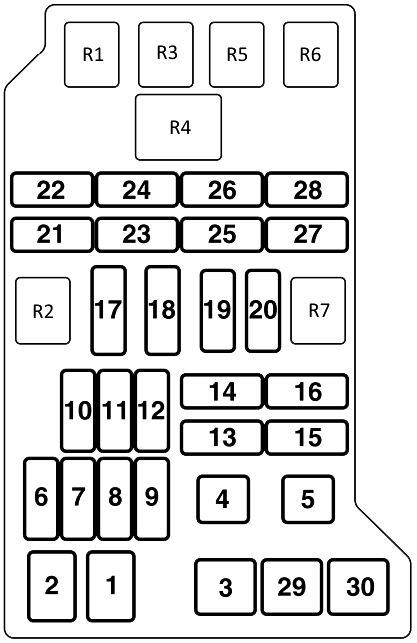
Cabin block
Located at the bottom of the instrument panel behind a protective cover.

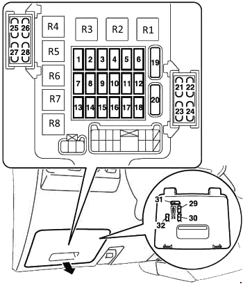
Fuse description
| 1 | 10A Ignition coils |
| 2 | 7.5A Control and measuring instruments |
| 3 | 7.5A Reverse lights |
| 4 | 7.5A Reserve |
| 5 | 7.5A Relay (heater, etc.) |
| 6 | 7.5A Heated mirrors |
| 7 | 30A Reserve |
| 8 | 7.5A Engine control unit |
| 9 | 15A Cigarette lighter |
| 10 | Reserve |
| 11 | 7.5A Electric mirror drive |
| 12 | 7.5A Engine control unit |
| 13 | Reserve |
| 14 | 15A Rear wiper |
| 15 | 15A Central lock |
| 16 | 10A Rear fog light |
| 17 | Not used |
| 18 | Not used |
| 19 | 30A Heater |
| 20 | 30A Heated rear window |
| 21 | 20A Luke |
| 22 | 10А ABS |
| 23 | 20A Seat heating |
| 24 | 10A Footwell and door sill lighting |
| 25 | 10A Transfer box control unit |
| 26 | 10А ENG/POWER |
| 27 | 10A Starter |
| 28 | Not used |
| 29 | 20A Spare fuse |
| 30 | 10A Spare fuse |
| 31 | 30A Spare fuse |
| 32 | 25A Spare fuse |
Fuse number 9 at 15A is responsible for the cigarette lighter.
Relay purpose
- R1 – Rear window defroster relay
- R2 – Front fan relay
- R3 – Power window relay
- R4 – Fuel pump relay 1
- R5 – Rear fog light relay
- R6 – Fuel pump relay 1
- R7 – Auxiliary equipment power outlet relay
- R8 – Rear fan relay
Blocks under the hood
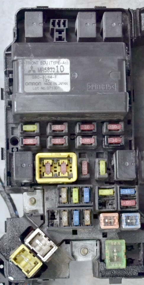
Main unit
The main unit with fuses and relays is located next to the battery on the left side of the engine compartment.
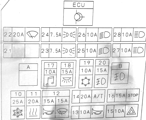
Appointment
| R1 | A/C Condenser Fan Motor Relay – High Speed |
| R2 | Horn relay |
| R3 | A/C condenser fan motor relay – low speed |
| R4 | Multifunctional control unit 1 |
| R5 | Windshield Defroster Relay – Windshield Wipers |
| R6 | Air conditioner compressor electromagnetic clutch relay |
| R7 | Reserve |
| 1 | 120A Fuse/relay block 1 in engine compartment, fog lights, headlights, tail lights (2001), multifunction control unit 1 (2002^) |
| 2 | 60A Fuse/Relay Block, Engine Compartment 1 |
| 3 | 40A Ignition switch |
| 4 | 40A Electric seats, electric window lifters |
| 5 | 20A Engine control |
| 6 | 20A Engine control |
| 7 | – |
| 8 | 15A Additional equipment |
| 9 | 25A Fuel filter heater |
| 10 | 25A Air conditioner |
| 11 | 20A Air conditioner |
| 12 | 15A Windshield Defroster Relay – Windshield Wipers |
| 13 | – |
| 14 | 20A Automatic transmission |
| 15 | 10A Generator, central locking, turn signals/emergency alarm |
| 16 | 15A Anti-lock braking system (ABS), brake lights |
| 17 | 10A Audio system, cigarette lighter , clock |
| 18 | 10A Air conditioning system, audio system, central locking, clock, ESP electronic control unit, interior lights, multifunction control unit 1, transfer case control unit |
| 19 | 10A Air conditioner |
| 20 | 20A Fog lights |
| 21 | 10A Audible signal |
| 22 | 20A Windshield wiper/washer |
| 23 | 10A Engine management system, rear (right) |
| 24 | 10A Rear left side marker lamp |
| 25 | 10A Low beam bulb (left) |
| 26 | 10A Low beam bulb (right) |
| 27 | 10A High beam bulb (left) |
| 28 | 10A High beam lamp (right) |
| 29 | Reserve |
| 30 | 40A Coolant heater |
Fuse number 17 at 10A is responsible for the additional cigarette lighter sockets.
Relay block
Scheme
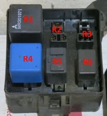
Description
- Solenoid valve relay
- Fuel heater relay
- Throttle servo relay
- Starter relay
- Main injection system relay
- Air conditioner compressor electromagnetic clutch relay
Individual fuses and relays can be installed outside these units, for example, the relay for the fuel pump motor or the ABS emergency braking system. Also, there can be high-power fuses on the positive terminal of the battery: 40/60A – ABS and 80A – Glow plugs.