The Mitsubishi Grandis minivan was produced in 2003, 2004, 2005, 2006, 2007, 2008, 2009, 2010 and 2011 with both petrol and diesel engines. In this article you will find a description of the Mitsubishi Grandis fuses and relays with block diagrams and their locations. Let’s highlight the cigarette lighter fuse.
The purpose of the fuses and relays in the blocks may differ from that shown and depends on the equipment level and year of manufacture.
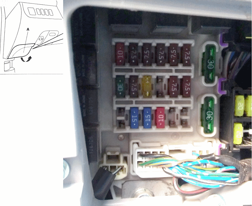
Block in the cabin
It is located under the instrument panel on the left side, behind the protective cover.
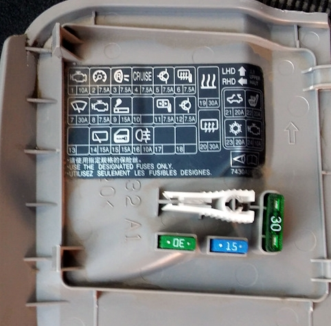
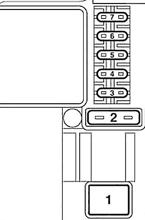
Example of a diagram from the block cover
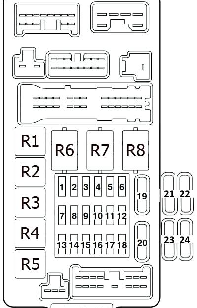
Scheme
Description
| 1 | 10A | Ignition system |
| 2 | 7.5A | Instrument cluster (panel) |
| 3 | 7.5A | Reversing lights, Automatic transmission control relay |
| 4 | 7.5A | Cruise control system |
| 5 | 7.5A | Relay |
| 6 | 7.5A | Remote control for exterior mirrors |
| 7 | 30A | Wipers and washers, Electronic control unit for lighting |
| 8 | 7.5A | Electronic control unit of the engine and automatic transmission (for cars with automatic transmission), electronic unit of the engine control system, fuel pump relay |
| 9 | 15A | Cigarette lighter |
| 10 | Reserve | |
| 11 | 7.5A | Electric mirrors |
| 12 | 7.5A | Engine control |
| 13 | 10A | Audio system, Radio |
| 14 | 15A | Rear window wiper/washer |
| 15 | 15A | Central lock |
| 16 | 10A | Rear fog light |
| 17 | Reserve | |
| 18 | 10A | Interior lighting lamps |
| 19 | 30A | Heater Fan Motor |
| 20 | 30A | Rear window defroster |
| 21 | 20A | Hatch drive electric motor |
| 22 | 20A | Seat heater |
| 23 | 20A | Rear air conditioner |
| 24 | 10A | Starter |
The fuse number 9 for 15A is responsible for the cigarette lighter. There is also another fuse in the block under the hood.
Decoding the relay
- Fuel pump relay (1)
- Front seat heating relay
- Fuel pump relay (2)
- Socket relay for connecting additional equipment
- Rear Fog Light Relay
- Electric window lifter relay
- Heater Fan Motor Relay
- Rear Window Defogger Relay
Blocks under the hood
They are installed in the left part of the engine compartment. They consist of the main fuse and relay block and an additional block.
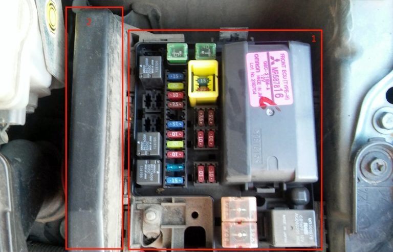
Main block
Example of a diagram from the block cover
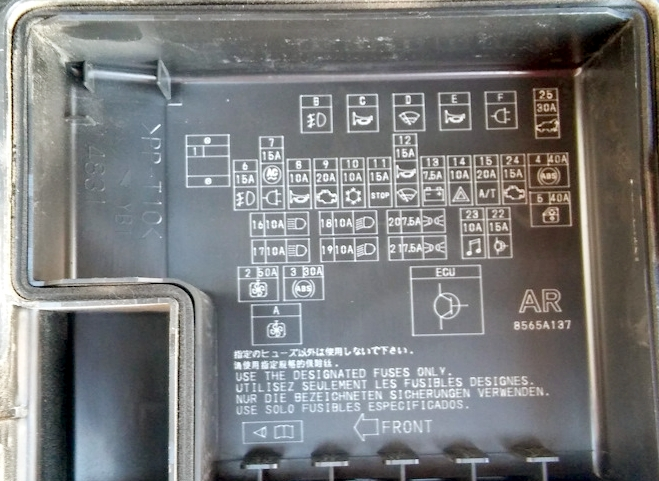
Scheme
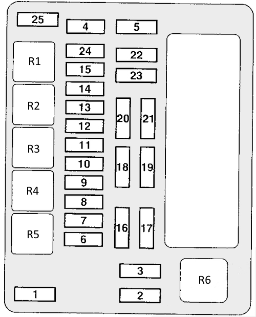
Purpose of fuses
| 1 | 60A | Instrument Panel Fuse/Relay Box 80A Battery/Spare |
| 2 | 50A | Electric motor of the cooling system fan |
| 3 | 30A | ABS system |
| 4 | 40A | Ignition switch chains |
| 5 | 40A | Electric window lifters |
| 6 | 15A | Fog lights |
| 7 | 15A/20A | AC power supply, power for additional power outlets |
| 8 | 10A | Sound signal |
| 9 | 20A | Engine management system |
| 10 | 10A | Air conditioning compressor electromagnetic clutch |
| 11 | 15A | Brake lights |
| 12 | 15A | Windshield heater, signal |
| 13 | 7.5A | Generator |
| 14 | 10A | Alarm |
| 15 | 20A | Electronic control unit of the gearbox |
| 16 | 10A | Right headlight high beam |
| 17 | 10A | Left headlight high beam |
| 18 | 10A | Right low beam headlight |
| 19 | 10A | Low beam left headlight |
| 20 | 7.5A | Tail light (right) |
| 21 | 7.5A | Tail light (left) |
| 22 | 15A | Reserve / Engine Management |
| 23 | 10A | Audio system |
| 24 | 15A | Fuel pump |
| 25 | 30A | Electric tailgate |
Relay designation
- Additional Equipment Power Connector Relay
- Horn or alarm relay
- Wiper relay
- Horn or alarm relay
- Fog light relay
- Cooling Fan Relay
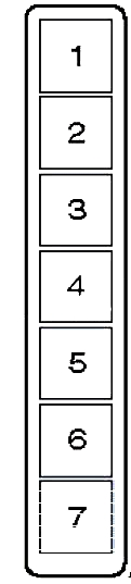
Additional block
Diesel
Scheme
Description
- Air conditioning compressor electromagnetic clutch relay
- Engine Management System Relay
- Electronic control unit relay of the gearbox
- Ignition relay
- Throttle Control Unit Relay
- Reserve
- Reserve
Petrol
Scheme
Designation
| 1 | 30A | Condenser fan |
| 2 | 30A | Engine control |
| 3 | 10A | Control flap |
| 4 | 10A | Ignition relay |
| 5 | 10A | Valve block |
| 6 | 7.5A | Electronic anti-theft device |
| 7 | 10A | Heating |