Mazda CX-5 (KF) (2nd generation) was produced in 2017, 2018, 2019, 2020, 2021, 2022. In this article, we will show a description of the fuses and relays of the Mazda CX-5 KF with block diagrams, photos and locations. We will note the cigarette lighter fuse.

The purpose of fuses and relays in the blocks may vary. Compare the description with your diagrams.
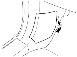
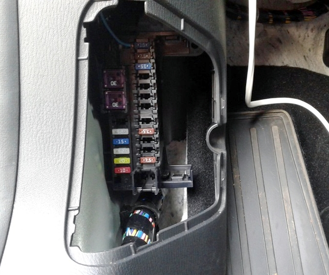
Cabin block
Located under a protective cover on the left pillar, under the instrument panel near the driver’s foot.
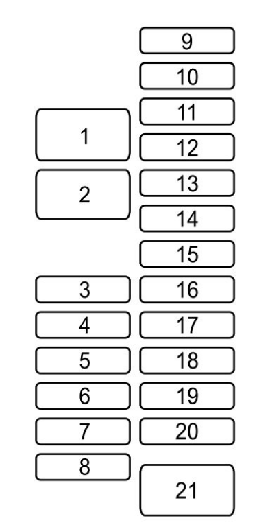
Description
| 1 | 30A P.SEAT D – Electric seat adjustment drive (for some versions) |
| 2 | 30A P.WINDOW 3 – Electric windows |
| 3 | 15A R.OUTLET3 – Additional electrical outlets |
| 4 | 25A P.WINDOW 2 – Electric windows |
| 5 | 15A SRS2/ESCL – Steering shaft lock |
| 6 | 25A D.LOCK – Central electric lock |
| 7 | 20A SEAT WARM – Electric seat heating (for some versions) |
| 8 | 10A SUNROOF – Sunroof (for some versions) |
| 9 | 15A F.OUTLET – Front electrical sockets (cigarette lighter) |
| 10 | 7.5A MIRROR – Electric drive for adjusting rear-view mirrors |
| 11 | 15A R.OUTLET1 – Rear electrical outlets (for some versions) |
| 12 | Reserve |
| 13 | Reserve |
| 14 | Reserve |
| 15 | Reserve |
| 16 | Reserve |
| 17 | 7.5A M.DEF – Electric heated exterior mirrors |
| 18 | 20A R.SEAT W – Seat heating |
| 19 | Reserve |
| 20 | 7.5A AT IND – Transmission Indicator |
| 21 | 30A P.SEAT P – Electric seat adjustment drive |
The cigarette lighter fuses are marked OUTLET at 15A and are located under numbers 3, 9 and 11. Another fuse and relays responsible for the operation of the power outlets can also be mounted in the unit under the hood.
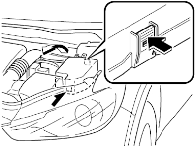
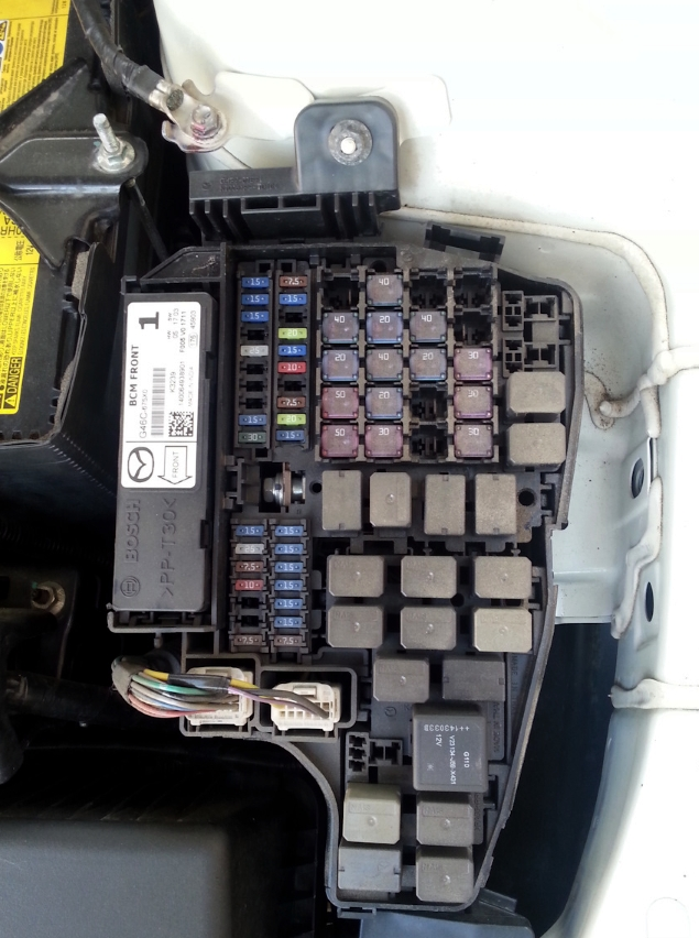
Block under the hood
Located on the left side of the engine compartment, next to the battery.
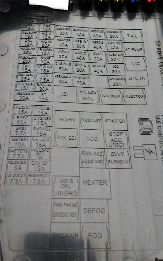
Fuses
Fuse diagram
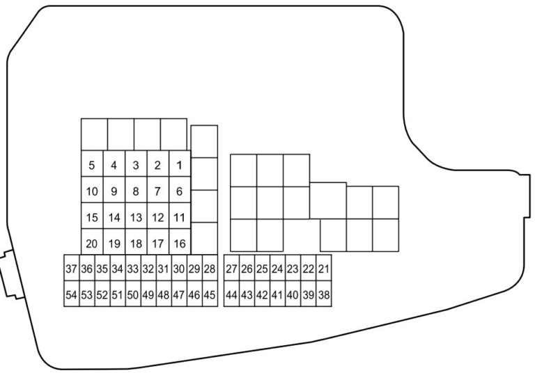
Purpose of fuses
| 1 | 30A ADD FAN GE – Engine cooling fan |
| 2 | 30A IG2 – Protection of various electrical circuits |
| 3 | 30A INJECTOR – Engine Management System |
| 4 | 40A FAN DE – Engine cooling fan |
| 5 | 30A P.WINDOW1 – Electric windows |
| 6 | Reserve |
| 7 | 40A ADD FAN DE – Engine cooling fan |
| 8 | 20A EVVT – Engine Management System |
| 9 | 40A DEFOG – Electric heated rear window |
| 10 | 40A DCDC DE – Protection of various electrical purposes |
| 11 | 30A FAN GE – Engine cooling fan |
| 12 | Reserve |
| 13 | Reserve |
| 14 | Reserve |
| 15 | 40A ENG.MAIN – Engine control system |
| 16 | 50A ABS/DSC M – Anti-lock braking system (ABS), traction control system (DSC) |
| 17 | 50A CABIN +B – Protection of various electrical circuits |
| 18 | 20A WIPER – Windshield wiper and washer |
| 19 | 40A HEATER – Heater / Air Conditioner |
| 20 | 30A DCDC REG – Protection of various electrical circuits |
| 21 | 7.5A ENGINE IG1 – Engine management system |
| 22 | 15A C/U IG1 – Protection of various electrical circuits |
| 23 | H/L LOW L HID L – Headlight (left), low beam headlight (left) |
| 24 | 15A H/L LOW R – Low beam headlight (right) |
| 25 | 15A ENGINE 3 – Engine control system |
| 26 | 15A ENGINE 2 – Engine control system |
| 27 | 15A ENGINE 1 – Engine control system |
| 28 | 15A AT – Transmission control system, ignition switch |
| 29 | 20A H/CLEAN – Headlight washer |
| 30 | 7.5A A/C – Air Conditioning |
| 31 | 15A – AT PUMP Transmission control system |
| 32 | 10A STOP – Brake lights, rear fog light |
| 33 | 15A R.WIPER – Rear window wiper |
| 34 | 20A H/L HI – High beam headlights |
| 35 | 15A HID R – Headlight (right) |
| 36 | 15A FOG – Front fog lights |
| 37 | 7.5A ENG.+B – Engine control system |
| 38 | 7.5A AUDIO2 – Audio system |
| 39 | 5A GLOW SIG – Engine Management System |
| 40 | 7.5A METER2 – Instrument cluster |
| 41 | 10A METER1 – Instrument cluster |
| 42 | 7.5A SRS1 – Airbags |
| 43 | 25A BOSE – Cars equipped with a Bose audio system |
| 44 | 15A AUDIO 1 – Audio system |
| 45 | 30A ABS/DSC S – Anti-lock braking system (ABS), traction control system (DSC) |
| 46 | 15A FUEL PUMP – Fuel system |
| 47 | 25A FUEL WARM – Fuel heating |
| 48 | TAIL – Dimensions |
| 49 | Reserve |
| 50 | 50A HAZARD – Hazard warning lights, turn signals, front and rear position lights, license plate lights |
| 51 | Reserve |
| 52 | 15A R.OUTLET2 – Electrical sockets |
| 53 | 15A HORN – Sound signal |
| 54 | 15A ROOM – Interior lighting ceiling |
To turn off the headlight washer, you need to remove fuse number 29 at 20A marked H/CLEAN .
Relay
Relay diagram
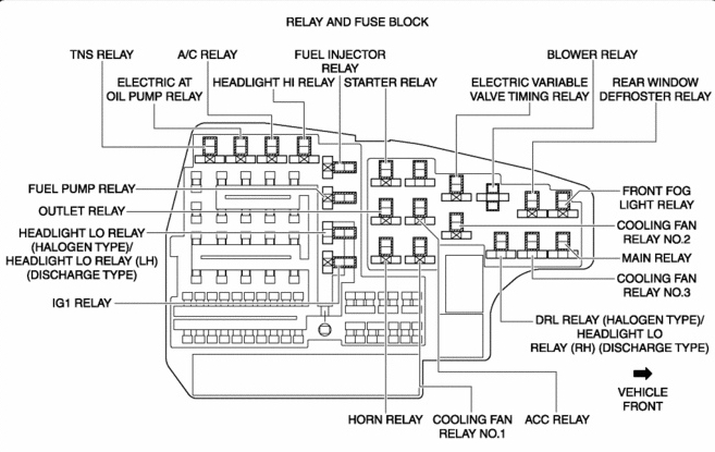
Relay designation
| TNS RELAY (TAIL) | TNS RELAY (DIMENSIONS) |
| A/C RELAY | AIR CONDITIONING RELAY |
| FUELINJECTOR RELAY | FUEL INJECTOR RELAY |
| ELECTRIC AT OR OIL PUMP RELAY | ELECTRIC TRANSMISSION RELAY OR TRANSMISSION OIL PUMP RELAY |
| HEADLIGHT HI RELAY | HEADLIGHT RELAY |
| STARTER RELAY | STARTER RELAY |
| BLOWER RELAY | FAN RELAY |
| ELECTRIC VARIABLE VALVE TIMING RELAY | ELECTRIC VALVE CHARGING RELAY |
| REAR WINDOW DEFROSTER RELAY | REAR WINDOW DEFROSTING RELAY |
| FUEL PUMP RELAY | FUEL PUMP RELAY |
| OUTLET RELAY | ELECTRICAL SOCKET RELAY |
| HEADLIGHT LO RELAY | HEADLIGHT RELAY (NEAR) |
| IG1 RELAY | IGNITION RELAY |
| FRONT FOG LIGHT RELAY | FRONT FOG LIGHT RELAY |
| COOLING FAN RELAY NO.2 | COOLING FAN RELAY #2 |
| MAIN RELAY | MAIN RELAY |
| COOLING FAN RELAY NO. 3 | COOLING FAN RELAY #3 |
| DRL RELAY | RELAY DHO |
| HORN RELAY | RELAY SIGNAL |
| COOLING FAN ACC RELAY | COOLING FAN RELAY |