The Mazda CX-7 crossover was produced in 2006, 2007, 2008, 2009, 2010, 2011 and 2012 mainly with 2.3 and 2.5 liter gasoline engines. During this time, the model has undergone restyling once. In this article, we will consider in detail the description of the Mazda CX7 fuses and relays with block diagrams and photo examples of execution. We note the cigarette lighter and headlight washer fuse.

The purpose of fuses and relays in the units may vary and depends on the year of manufacture and the level of electrical equipment. Check your diagrams on the protective cover.
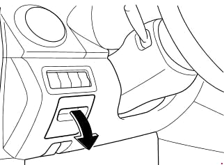
Cabin block
It is located at the bottom of the instrument panel on the driver’s side behind a protective cover. To access it, pull the cover towards you.
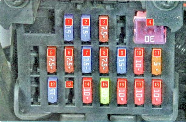
Description
| 1 | 15A OUTLET 1 – Additional electrical outlet in the cabin, cigarette lighter |
| 2 | 15A OUTLET 2 – Additional electrical socket in the trunk |
| 3 | 7.5A P.MIR – Electric mirror |
| 4 | 30A WIPER – Windshield wiper and washer |
| 5 | 7.5A M.DEF – Mirror heater |
| 6 | 7.5A ENG BAR 3 – Air flow meter, EGR valve |
| 7 | 15A P.WIND – Electric window lifters |
| 8 | 7.5A A/B – Passive safety system, Airbags |
| 9 | 15A ENGINE – Engine control system |
| 10 | 10A METER – Instrument cluster |
| 11 | 5A BBS – Security construction |
| 12 | 15A ROOM – Interior lighting, Audio system |
| 13 | Reserve |
| 14 | 10A ILLUMI A/C – Instrument panel illumination |
| 15 | 20A SEAT – Seat heater |
| 16 | 10A A/C – Air conditioning |
| 17 | 10A R.WIP – Rear window wiper and washer |
| 18 | 10A R.FOG – Rear fog lamp |
Fuses numbers 1 and 2 at 15A are responsible for the operation of the cigarette lighters.
Option 2
Scheme
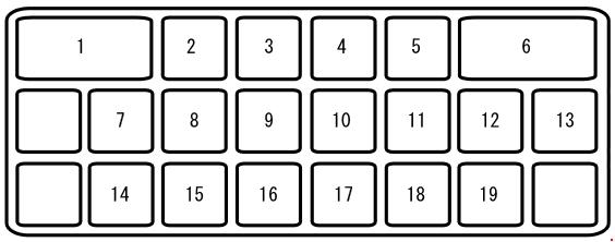
Fuse designations
| 1 | 30A P.WIND2 – Electric window lifters |
| 2 | 15A OUTLET 1 – Additional electrical outlet in the cabin, cigarette lighter |
| 3 | 7.5A P.MIR – Electric mirror |
| 4 | 15A OUTLET 2 – Additional electrical outlet |
| 5 | Reserve |
| 6 | 30A WIPER – Windshield wiper and washer |
| 7 | 7.5A M.DEF – Mirror heater |
| 8 | 7.5A ENG BAR 3 – Air flow meter, EGR valve |
| 9 | 15A P.WIND – Electric window lifters |
| 10 | 7.5A A/B – Advanced passive safety system, airbags |
| 11 | 15A ENGINE – Engine control system |
| 12 | 15A METER – Instrument cluster |
| 13 | 10A ILLUMI – Instrument panel lighting |
| 14 | 15A ROOM – Audio system, interior overhead lighting |
| 15 | 20A SEAT – Seat heater |
| 15 | R.FOG – Rear fog lights |
| 16 | 10A A/C – Air conditioning |
| 16 | SIREN – Security alarm |
| 17 | 20A SEAT – Seat heater |
| 18 | 10A A/C – Air conditioning |
| 19 | 10A R.WIP – Rear Wiper and Washer |
In this version, fuses numbered 2 and 4 at 15A are responsible for the cigarette lighter according to the diagram.
Block under the hood
There are two blocks under the hood of the Mazda CX 7: (1) the main fuse and relay block and (2) the additional relay block.
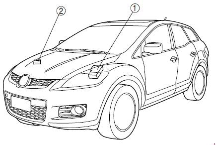
Main unit
To access the unit, you must lift the protective cover.

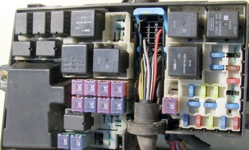
Scheme
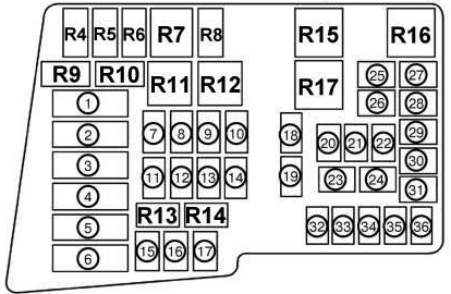
Under numbers 1 to 6 is a group of fuses in the form of a fuse link. In the photo, it is covered with a cover.
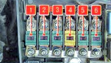
Fuse assignment 1
| 1 | 40A IGN2 – Ignition system |
| 2 | 40A BLOWER – Electric fan motor |
| 3 | 60A BTN – Protection of various electrical circuits |
| 4 | 40A FAN 2 – Radiator fan |
| 5 | 40A IGN1 – Ignition system |
| 6 | 40A FAN1 – Radiator fan |
| 7 | 40A P.SEAT – Electric seat |
| 8 | 30A INJ – Fuel Injection System |
| 9 | 20A ROOF – Roof hatch |
| 10 | 30A BOSE – Bose Audio System |
| 11 | 30A ENGINE – Engine control system |
| 12 | 20A D.LOCK – Electric locks |
| 13 | 30A P.WIND – Electric windows |
| 14 | 30A FUEL PUMP – Fuel pump |
| 14 | 40A IG KEY2 – Ignition system |
| 15 | 40A ABS1 – ABS |
| 16 | 20A ABS2 – ABS |
| 17 | 7.5A DSC – DSC system |
| 18 | 20A FOG – Fog lights |
| 19 | 30A DEF – Rear window heater |
| 20 | 15A TNS – Parking lot lighting, license plate lighting, entrance system lighting |
| 21 | 10A A/C – Air conditioning |
| 22 | 20A ETC – Accelerator Pedal Position Sensor |
| 23 | 15A H/LH1 – Headlight leveling control |
| 24 | 15A DRL – Daytime Running Lights |
| 25 | 15A H/L LO RH – Right low beam headlight |
| 26 | 15A H/L LO LH – Left low beam headlight |
| 27 | 7.5A ENG BAR 2 – PCM (power distribution module) |
| 28 | 10A ECM – Engine Management System |
| 29 | 15A ENG BAR 1 – Air flow meter, EGR valve |
| 30 | 20A RWIND2 – Electric window lifters |
| 31 | 10A STOP – Stop signals |
| 32 | 20A HORN – Sound signal |
| 33 | 25A ENGB+ – PCM (power distribution module) |
| 34 | 10A HAZARD – Hazard warning lights, turn signals |
Fuse assignment 2
| 1 | PCS – Pre-emergency Safety System |
| 2 | 40A BLOWER – Electric fan motor |
| 3 | 30A FUEL PUMP – Fuel pump |
| 4 | 40A FAN 2 – Radiator fan |
| 5 | 40A IG KEY1 – Ignition system |
| 6 | 40A FAN1 – Radiator fan |
| 7 | 30A P.SEAT (D) – Electric driver’s seat |
| 8 | 30A INJ1 – Fuel injection system |
| 9 | P.SEAT – Electric passenger seat |
| 10 | 30A BOSE – Audio system |
| 11 | 30 ENGINE – Engine management system |
| 12 | 20A D.LOCK – Electric locks |
| 13 | 30A P.WIND – Electric window lifters |
| 14 | 40A IG KEY2 – Ignition system |
| 15 | 40A ABS1 – ABS |
| 16 | 20A ABS2 – ABS |
| 17 | DSC – Directional Stability System |
| 18 | 20A H/L/ CLEAN/ ROOF – Headlight cleaner |
| 19 | 30A DEF – Rear window defroster |
| 20 | 15A TNS – Parking lot lighting, license plate lighting, entrance system lighting |
| 21 | 10A A/C – Air conditioning |
| 22 | 20A TRAILER/TCM – FUELS |
| 23 | 15A HEAD HI RH – Right high beam headlight |
| 24 | 15A HEAD HI LH – Left high beam headlight |
| 25 | 15A HEAD LO RH – Right low beam headlight |
| 26 | 15A HEAD LO LH – Left low beam headlight |
| 27 | 20A ETC – Accelerator Pedal Position Sensor |
| 28 | 7.5A ENG BAR 2 – PCM (power distribution module) |
| 29 | 10A ECM – Engine Control System |
| 30 | 10A INJ1 – Fuel injection system |
| 31 | 15A ENG BAR 1 – Air flow meter, EGR valve |
| 32 | 15A FOG – Fog lights |
| 33 | 10A STOP – Stop signals |
| 34 | 20A HORN – Sound signal |
| 35 | 25A ENGB+ – PCM (power distribution module) |
| 36 | 10A HAZARD – Hazard warning lights, turn signals |
Fuse number 18 is responsible for the headlight washer.
Relay description
| R4 | Rear window heating relay |
| R5 | Relay for controlling lighting lamp circuits |
| R6 | Drive-by-wire relay |
| R7 | Headlight relay |
| R8 | Backup headlight relay |
| R9 | Fuel pump relay |
| R10 | Starter relay #2 |
| R11 | Cooling system fan relay #2 |
| R12 | Fan relay |
| R13 | Fuel pump speed control relay |
| R14 | Injector relay |
| R15 | Starter relay #1 |
| R16 | Main relay |
| R17 | Cooling system fan relay #1 |
Relay block
Scheme
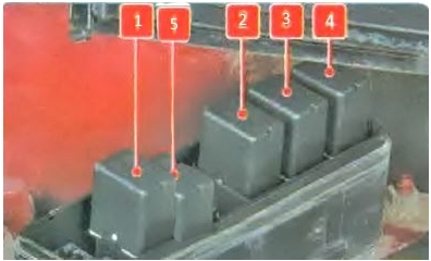
Transcript
- Rear fog lamp relay
- Fog light relay
- Air conditioner relay
- Horn relay
- Brake light relay