The Volkswagen Jetta 6 generation was presented in 2010 in the USA. Sales began in Europe in 2011. In Russia, this car was produced in 2012, 2013, 2014, 2015, 2016, 2017, 2018 and 2019. During this time, it underwent a restyle. In this publication, we will provide a description of the fuse and relay blocks of the Volkswagen Jetta 6, show diagrams and photos of the blocks in which they are located. We will highlight the fuse responsible for the cigarette lighter. We will also show the location of all electronic control units and offer a service manual for downloading.

General arrangement of control units
Scheme
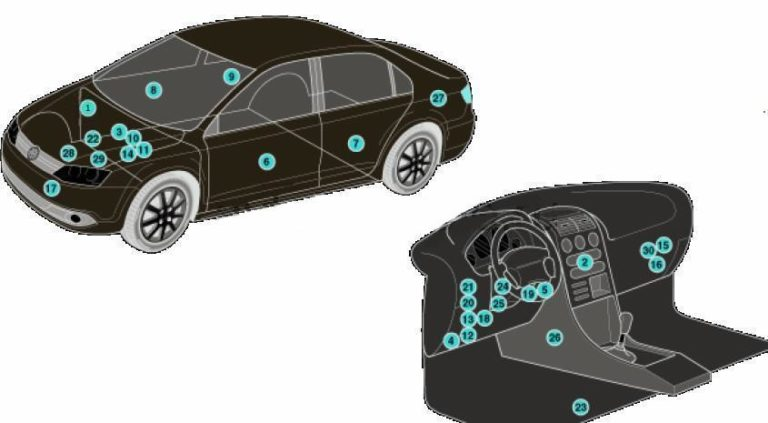
Description
| 1 | ABS electronic control unit |
| 2 | Electronic air conditioning control unit |
| 3 | Rechargeable battery |
| 4 | Diagnostic Connector (DLC) |
| 5 | Diagnostic unit |
| 6 | Driver’s door electrical control unit |
| 7 | Left rear door electrical control unit |
| 8 | Passenger door electrical control unit |
| 9 | Right rear door electrical control unit |
| 10 | Electronic Engine Control Module (ECM) |
| 11 | Fuse/relay block, engine compartment |
| 12 | Fuse/relay block, instrument panel 1 |
| 13 | Fuse/relay block, instrument panel 2 |
| 14 | Glow plug control unit – under the fuse/relay block in the engine compartment |
| 15 | Headlight leveling control unit |
| 16 | Heater fan motor resistor next to heater fan motor |
| 17 | Sound signal |
| 18 | Ignition switch control unit (some models) – in the instrument panel fuse/relay block 2 |
| 19 | Control unit for remote central locking and engine start system |
| 20 | Multifunction control unit – functions: Anti-theft system, central locking, charging system, door function control units, electrical load control, exterior lights, footwell lights, fuel filler flap opening drive, fuel pump, heated rear-view mirrors, heated rear window, horn, immobilizer, turn signals/hazard alarm, instrument cluster illumination, interior lights, remote central locking and engine start system, rain/sunlight sensor, brake lights, windshield wiper/washer |
| 21 | Parking system control unit |
| 22 | Power steering control unit – on the steering rack |
| 23 | Seat heating control unit – under the driver’s seat |
| 24 | Steering column electrical control unit |
| 25 | Steering column lock control unit |
| 26 | SRS electronic control unit |
| 27 | Trailer electrical equipment control unit |
| 28 | Transmission Control Module (TCM) (DSG transmission) |
| 29 | Transmission Control Module (TCM) – with automatic transmission |
| 30 | Voltage stabilizer unit |
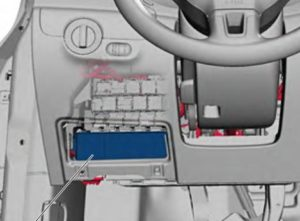
Blocks in the cabin
Fuse block
Located under the panel. Remove the cover to access.


Marking
Option 1
| F1 | |
| F2 | (5A) Steering column lock |
| F3 | (10A) Instrument cluster |
| F4 | |
| F5 | |
| F6 | (10A) Multifunction control unit |
| F7 | (5A) Fog light relay (AW0 only), switch and instrument cluster backlight dimmer (AW0 only), license plate light, on-board power supply control unit (AW1 only) |
| F8 | (7.5A) Windshield washer pump and headlight cleaning system switch, windshield washer pump |
| F9 | (5A) SRS system, airbag |
| F10 | (10A) Right steering column switch |
| F11 | |
| F12 | |
| F13 | (5A) Electrochromic interior mirror, light sensor, parking assistant control unit, air pollution sensor, high pressure sensor, Climatronic control unit, tire pressure monitoring button, reversing light switch, left washer jet heating resistor, heater |
| F14 | (10A) Left steering column switch, ABS control unit, lighting switch, fuel pump control unit |
| F15 | (10A) Switch and instrument cluster backlight brightness control, headlight range control, auxiliary heater relay, air flow meter, crankcase ventilation system heating resistor, left headlight, left headlight range control actuator, right headlight range control actuator |
| F16 | (10A) Engine control |
| F17 | |
| F18 | (15A) Left headlight |
| F19 | (15A) Right headlight |
| F20 | (10A) Automatic transmission control unit, selector sensor control unit, Tiptronic switch, Climatronic control unit, ignition and starter switch |
| F21 | |
| F22 | (10A) Ignition and starter switch, converter unit, anti-theft alarm buzzer, interior security sensor, alarm siren relay, two-tone buzzer relay |
| F23 | (10A) On-board network control unit, lighting switch, rain and light sensor, magnetic field sensor for compass |
| F24 | (10A) On-board network control unit, adaptive lighting system and headlight range control unit |
| F25 | (15A) Transmission |
| F26 | (15A) Brake booster vacuum pump |
| F27 | |
| F28 | (40A) Coolant heater, Auxiliary heater relay |
| F29 | (1A) Multifunction control unit |
| F30 | (20A) Cigarette lighter , sockets |
| F31 | (30A) Light switch |
| F32 | (30A) Light switch |
| F33 | (40A) Heater and mode selector switch, supply fan relay, air conditioning control unit, supply fan switch |
| F34 | (15A) Left headlight, instrument cluster control unit |
| F35 | (10A) Steering column control unit, instrument cluster control unit, horn switch, data bus diagnostic interface |
| F36 | (25A) Multifunction control unit |
| F37 | (15A) Left headlight |
| F38 | (15A) Right headlight |
| F39 | (15A) Low beam headlights |
| F40 | (15A) Trailer electrical control unit |
| F41 | (15A) Trailer electrical control unit |
| F42 | (20A) Trailer electrical control unit |
| F43 | (30A) Passenger door electrical control unit |
| F44 | (25A) Rear window heating relay |
| F45 | (25A) Driver’s door control unit, front passenger’s door control unit |
| F46 | (25A) Left rear door control unit, right rear door control unit |
| F47 | (15A) Fuel pump |
| F48 | (20A) Multifunction control unit |
| F49 | (40A) Air conditioner/heater |
| F50 | (30A) Seat heater |
| F51 | (20A) Hatch |
| F52 | (20A) Audible signal |
| F53 | (15A) Seat heater |
| F54 | (15A) Rear fog lights |
| F55 | (20A) Lighting switch, left steering column switch |
| F56 | – |
| F57 | (15A) Audio system, navigation system |
| F58 | (1A/30A) Telephone receiver-transmitter, inverter with socket, 12 V – 230 V |
| F59 | (30A) Audio output amplifier |
| F60 | (30A) Coolant heater |
Fuse number 30 at 20A is responsible for the cigarette lighter.
Option 2
| F1 | (10A) Washer jet heating resistor |
| F2 | (5A/7.5A) Steering column lock |
| F3 | (10A) Instrument cluster |
| F4 | (2A/10A) Receiving – transmitting device of the telephone |
| F5 | (7.5A) Left rear fog light |
| F6 | (10A) Multifunction control unit, Rear view camera |
| F7 | (5A) Fog light relay, switch and instrument cluster dimmer, license plate light |
| F8 | (7.5A) Windshield washer pump and headlight cleaning system switch, windshield washer pump |
| F9 | (5A) Airbag control unit, (15A) Seat occupancy detection system control unit |
| F10 | (10A) Right steering column switch |
| F11 | (10A) Left headlight (Gas discharge headlight) |
| F12 | (10A) Right headlight, (Gas discharge headlight) |
| F13 | (5A) Electrochromic interior mirror, light sensor, parking assistant control unit, air pollution sensor, high pressure sensor, Climatronic control unit, tire pressure monitoring button, ASR and ESP off button, reversing light switch, start-stop mode switch, left washer jet heating resistor, right washer jet heating resistor, mirror adjustment switch, exterior mirror heating button, adaptive lighting and headlight range control unit |
| F14 | (10A) Left steering column switch, ABS control unit, fuel pump control unit, trailer recognition control unit, voltage stabilizer, inverter with socket, 12 V – 230 V, data bus diagnostic interface |
| F15 | (10A) Connector, 16-pin, (Diagnostic connector), switch and instrument cluster backlight brightness control, headlight range control, supply fan relay, air flow meter, crankcase ventilation heating resistor, vibration suppression system control unit, left headlight range control actuator, right headlight, right headlight range control actuator |
| F16 | (10A) Relay for additional cooling system pump, fuel pump, electric drive key. |
| F17 | (10A) Anti-theft system and its relay |
| F18 | (15A) Left headlight |
| F19 | (15A) Right headlight |
| F20 | (10A) Ignition and starter switch, Tiptronic switch, automatic transmission control unit, selector lever sensor control unit, Climatronic control unit, radio signal receiver for additional liquid heater |
| F21 | (15A/20A) On-board electrical system control unit, two-tone horn relay, high-tone horn, low-tone horn |
| F22 | (7.5A/20A) Ignition and starter switch, converter unit, interior security sensor, alarm siren relay, anti-theft alarm sound signal |
| F23 | (10A) On-board network control unit, lighting switch, rain and light sensor, magnetic field sensor for compass |
| F24 | (10A) Adaptive lighting and headlight range control unit |
| F25 | (15A) Transmission, Automatic Transmission Selector |
| F26 | (15A) Brake booster vacuum pump |
| F27 | (1A) Airbag coil cable with contact ring |
| F28 | (40A) Relay for operation in autonomous heater mode |
| F29 | (1A) Multifunction control unit, Ignition and starter switch |
| F30 | (20A) Cigarette lighter, sockets |
| F31 | (30A) Light switch |
| F32 | (20A) Light switch |
| F33 | (40A) Heater and mode selector switch, supply fan relay, air conditioning control unit, supply fan switch |
| F34 | (15A) Left high beam headlight bulb, right high beam headlight bulb, instrument cluster control unit |
| F35 | (10A) Steering column control unit, diagnostic data bus interface, horn switch |
| F36 | (25A) Multifunction control unit |
| F37 | (15A) Left headlight, left daytime running light section lamp |
| F38 | (15A) Right headlight, right daytime running light section lamp |
| F39 | (20A) Low beam relay |
| F40 | (15A) Trailer electrical control unit |
| F41 | (15A) Trailer electrical control unit |
| F42 | (20A) Trailer electrical control unit |
| F43 | (30A) Passenger door electrical control unit |
| F44 | (30A) Rear window heating relay, rear window heating, on-board network control unit |
| F45 | (30A) Driver’s door control unit, front passenger’s door control unit |
| F46 | (30A) Left rear door control unit, right rear door control unit |
| F47 | (15A) Fuel pump |
| F48 | (20A) Multifunction control unit |
| F49 | (40A) Supply fan, Climatronic control unit |
| F50 | (30A) Seat heater |
| F51 | (20A) Hatch |
| F52 | (20A) Audible signal |
| F53 | (15A) Driver’s seat lumbar support position adjustment switch |
| F54 | (15A) Fog light relay |
| F55 | (20A) Lighting switch, left steering column switch |
| F56 | (10A) Electric drive control electronics and electric drive power circuits |
| F57 | (15A/25A) Audio system, navigation system |
| F58 | (30A) Inverter with socket, 12 V |
| F59 | (15A) Fan unlock relay, battery |
| F60 | (30A) Auxiliary heater control unit |
Fuse number 30 at 20A is responsible for the cigarette lighter.
Relay block
Located above the fuse box.
Option 1
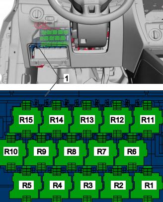
Relay purpose
- Converter, E-Box Low, (AW0)
- Supply air fan relay
- Auxiliary heater operating relay
- Fuel Pump (FP) Relay, Engine Component Power Supply Relay, Auxiliary Coolant Pump Relay
- Low beam relay
- Supply air fan relay
- Terminal 75, power relay 1
- Two-tone signal relay, Headlight washer relay
- Power supply relay (terminal 50)
- Terminal 15, power relay 2
- Rear window heating relay
- Fuel pump relay 2, Temperature relay, Cold start injector relay, Fuel primer relay
- Power supply relay (terminal 50)
- Terminal 15, power relay
- Fog light relay
Option 2
Scheme
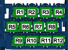
Transcript
- R1 – two-tone signal relay, headlight washer relay
- R2 – power supply relay (terminal 50), starter relay 2
- R3 – Fuel pump relay, cold start relay
- R4 – Coolant circulation pump relay, fuel pump relay
- R5 – Terminal 75, power relay 1
- R6 – Power supply relay (terminal 50), starter relay
- R7 – Terminal 15, power relay
- R8 – Low beam relay
- R9 – Terminal 15, power relay 2
- R10 – Terminal 75, power relay 1, changeover
- R11 – Fog light relay, fan relay
- R12 – Converter
Block under the hood
It is located on the right side, next to the battery and covered by a protective cover.
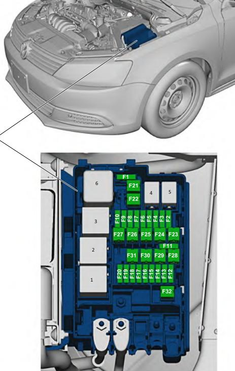
Description
| F1 | |
| F2 | (10A/15A) Engine control, Engine electronic components power supply relay |
| F3 | (5A) Cooling system fan motor, Heating relay |
| F4 | (5A/10A/15A) Engine management, Coolant pump, Lambda sensor heating element |
| F5 | (5A/10A/20A) Lambda sensor heating element, Fuel system diagnostic pump, Air flow meter, Brake system vacuum pump |
| F6 | (5A/10A/15A) Fuel System Diagnostic Pump, Fuel Tank Shutoff Valve, Secondary Air Pump Relay |
| F7 | (5A/20A) Engine Control (Ignition Coil), Fuel Pressure Regulator |
| F8 | (10A) Engine control (Throttle body, Bypass valve, Clutch pressure regulator..) |
| F9 | (5A/15A) Glow plug control unit, fuel pump relay |
| F10 | (5A) Speed sensor, brake light switch, brake booster relay |
| F11 | |
| F12 | (5A/20A) Coolant circulation pump, Ignition coil |
| F13 | (5A) Water pump (20A) Brake booster relay |
| F14 | (5A) Engine control, Main relay |
| F15 | (30A) Voltage stabilizer unit |
| F16 | (30A) ABS/ESP system |
| F17 | (30A) Transmission |
| F18 | (20A) Mechatronic unit DSG gearbox |
| F19 | (1A) Multifunction control unit |
| F20 | (30A) Wiper and washer relay |
| F21 | (50A) Exhaust air pump |
| F22 | (40A) Auxiliary air heater heating element |
| F23 | (40A) ABS/ESP system |
| F24 | (50A) Trailer electrical control unit |
| F25 | (50A) Main ignition circuits, Power supply relay terminal 15 |
| F26 | (60A) Glow plugs (40A) Secondary air pump relay |
| F27 | (50/60A) Cooling system fan motor |
| F28 | (40A) Multifunction control unit |
| F29 | (40A) Multifunction control unit |
| F30 | (50A) Auxiliary circuits |
| F31 | (30A) Audio output amplifier |
| F32 | (40A) Coolant heater |
Relay purpose
- Secondary air pump relay
- Cooling system pump relay
- Air supply relay, Power supply relay terminal 30
- –
- –
- Glow plug relay
Fuse Department
High-power fuses in the form of fuse links are located on the side of the unit.
Scheme
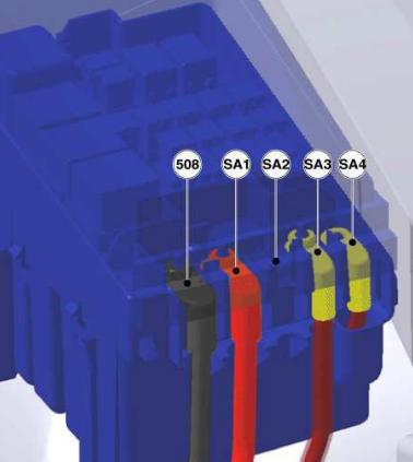
Marking
- 508 – threaded connection (30) on the switching block
- SA1 – 200A Generator
- SA2 –
- SA3 – 80A Steering
- SA4 – 80A Interior, cl. 30, fuse power supply