Volkswagen Teramont 1st generation was produced in 2017, 2018, 2019, 2020, 2021, 2022, 2023. During this time, the model has undergone restyling. In some countries, this model is also known as Volkswagen Atlas . In our post you will find a description of the fuses and relays of the Volkswagen Teramont with block diagrams, location and photo examples of execution. Pay attention to the cigarette lighter fuse.

The purpose of fuses and relays may differ from those shown and depends on the year of manufacture, equipment and country of delivery. In case of difficulties, contact your nearest dealer.
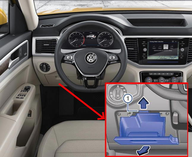
Cabin block
The fuse and relay block is located in the lower part of the instrument panel on the driver’s side. To access it, you must remove the glove compartment.
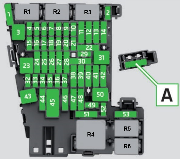
Description
| 1 | Not used |
| 2 | 10A Steering column electronics control module |
| 3 | 30A Rear supply air fan control module |
| 4 | 7.5A On-board network control module |
| 5 | 7.5A On-board diagnostic interface data bus |
| Remote start system relay | |
| 6 | 7.5A Selector mechanism |
| Ignition solenoid | |
| 7 | 10A Heater and air conditioning control |
| Air conditioning rear display control unit | |
| Rear window heater relay | |
| Air conditioner clutch relay | |
| Tire pressure monitoring module | |
| 8 | 7.5A Diagnostic connection |
| Electromechanical parking brake button | |
| Driving profile selection control head | |
| Rain/light sensor | |
| Rotary light switch | |
| Cornering light and headlight range control module | |
| Lamp 1 of the instrument panel contour lighting | |
| Lamp 2 of the instrument panel contour lighting | |
| Lamp 3 of the instrument panel contour lighting | |
| Garage door opener control head | |
| 9 | 7.5A Steering column electronics control unit |
| Ignition/starter switch | |
| 10 | 7.5A Front information display control head |
| 11 | 40A On-board network control module |
| 12 | 20A Information electronics control module 1 |
| 13 | Not used |
| 14 | 40A Supply air fan control module |
| 15 | 10A Steering column lock electronic control unit |
| 16 | 7.5A USB hub |
| USB connection 1 | |
| 17 | 7.5A Instrument cluster |
| Emergency call module and communication unit control module | |
| 18 | 7.5A Selector mechanism |
| Peripheral camera control module | |
| Back cover handle | |
| 19 | 7.5A Access/Start System Interface |
| 20 | Not used |
| 21 | 15A All-wheel drive control module |
| 22 | 15A Towing Recognition Control Module |
| 23 | 30A Power sunroof control module |
| 24 | 40A On-board network control module |
| 25 | 30A Driver’s door control module |
| Driver’s side rear window motor | |
| 26 | 30A On-board network control module |
| 27 | 30A On-board network control module |
| 28 | 25A Towing Recognition Control Module |
| 29 | 5A Refrigerant circuit pressure sensor |
| 30 | 10A Remote Start System Relay |
| 31 | Rear cover control module |
| 32 | 10A Blind Spot Detection Control Module |
| Blind Spot Detection Control Module 2 | |
| Parking assistance system control unit | |
| Front camera of the driver assistance system | |
| Remote control module | |
| 33 | 7.5A Airbag control module |
| Front seat passenger presence sensor | |
| Passenger presence detection system control module | |
| 34 | 7.5A Refrigerant circuit pressure sensor |
| Switch module in the instrument panel, in the center / Front passenger airbag deactivation indicator lamp | |
| Interior rearview mirror | |
| Rotary light switch | |
| Relay sockets | |
| 35 | 7.5/10A Diagnostic connector |
| 36 | 7.5/10A Headlight right |
| 37 | 7.5/10A Headlight left |
| 38 | 25A Towing Recognition Control Module |
| 39 | 30A Front passenger door control module |
| Passenger side rear window motor | |
| 40 | Socket 20A 12 V |
| 12 V socket 2 | |
| 12 V socket 3 | |
| 41 | Not used |
| 42 | 40A On-board network control module |
| 43 | 30/40A Digital Audio Control Module |
| 44 | 15A Towing Recognition Control Module |
| 45 | 15A Fan 1 front left seat backrest |
| Left front seat cushion fan 1 | |
| 46 | Converter 7.5/30A with socket, 12V-230V |
| 47 | 15A Rear window wiper motor |
| 48 | Not used |
| 49 | 7.5A Starter Relay 1 |
| Starter relay 2 | |
| Remote start system relay | |
| 50 | 40A Rear Cover Control Module |
| 51 | 25A Air conditioning rear display control unit |
| 52 | Not used |
| 53 | 30A Rear window defroster relay |
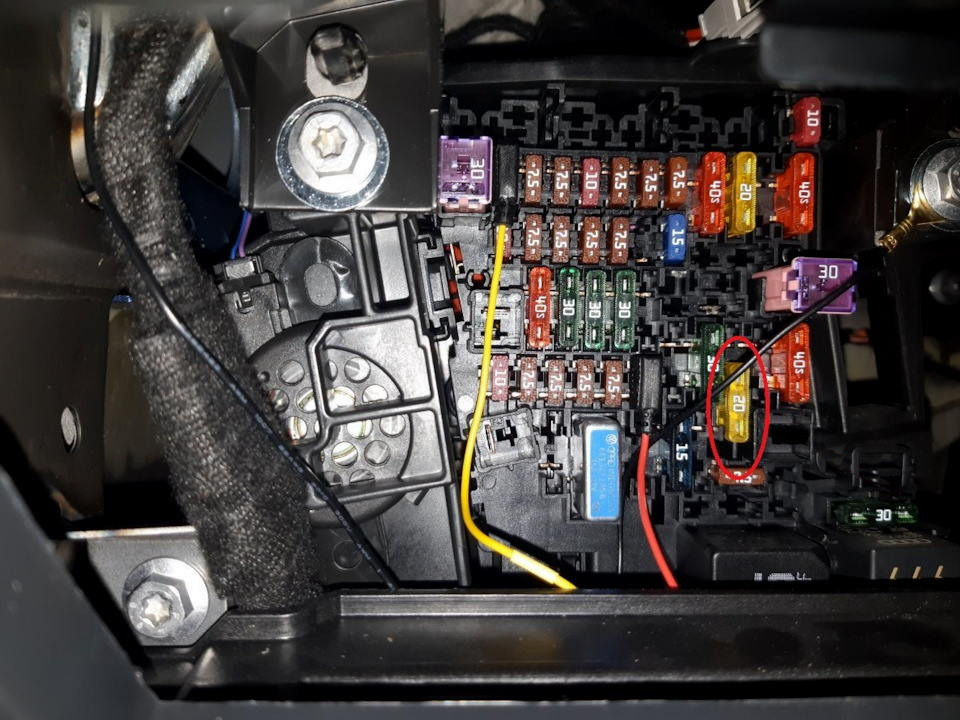
Fuse No. 40, 20A, is responsible for the cigarette lighter.
Relay
- R1 Reductant dosing system relay -J963-
- R2 –
- R3 –
- R4 Terminal 15 power relay -J329-
- R5 Rear window heating relay -J9-
- R6 Socket relay -J807-
Additional fuses
Scheme
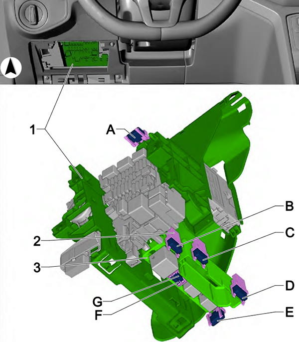
Marking
| A | Not used |
| B | 15A Right front seat adjustment control head |
| Right front seat backrest fan 1 | |
| Right front seat cushion fan 1 | |
| C | Not used |
| D | 7.5A USB charging port 1 |
| AND | 5A Refrigerant circuit pressure sensor |
| F | Not used |
| G | 25A Electric trailer brake position sensor |
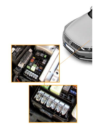
Blocks under the hood
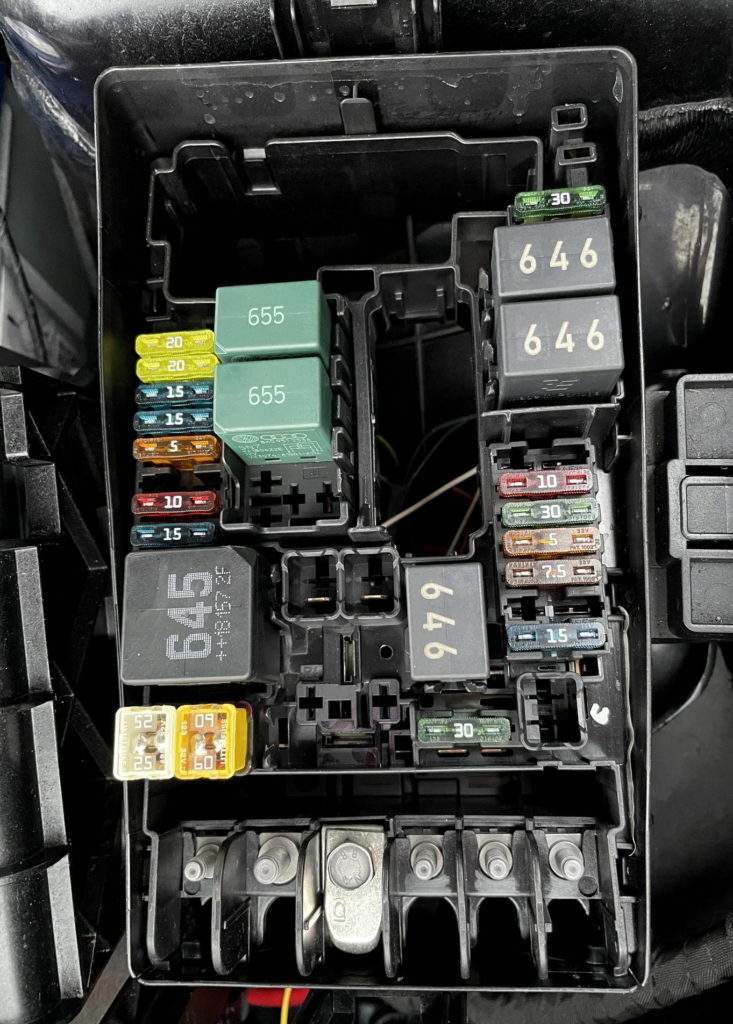
Main unit
The main fuse and relay block under the hood is located on the left side of the engine compartment, next to the battery.
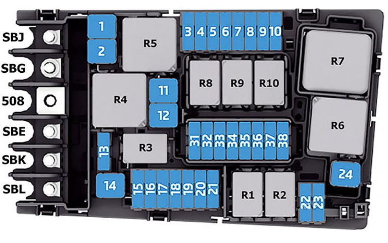
Appointment
| SBJ | Power supply to 125A fuses (on fuse panel C) No. 4, 12, 14, 22, 38, 40, 42, 46, 51, 53. |
| Relay sockets | |
| Power relay terminal 15 | |
| Automatic switch 1 front passenger seat adjustment | |
| Trailer circuit breaker | |
| SBG | 400A generator with voltage regulator |
| 508 | Screw connection – terminal 30 (on the electronics unit) / battery |
| SBE | 80A Power steering control module |
| SBC | 80A fuse power supply (on fuse panel C): No. 3, 15, 19, 21, 23, 28, 30, 43, 45, 50 |
| SBL | 80A Radiator fan |
| SB1 | ABS control module 25/40A |
| SB2 | ABS control unit 60A |
| SB3 | 15A Engine Control Module |
| SB4 | 10A Fuel tank leak detection control module |
| Radiator fan (radiator fan control module, radiator fan) | |
| Oil level temperature sensor | |
| Coolant shut-off valve | |
| Camshaft adjustment valve 1 | |
| Coolant circulation valve | |
| Intake manifold guide control valve | |
| Exhaust camshaft adjustment valve 1 | |
| EVAP canister purge control valve 1 | |
| Turbocharger recirculation valve | |
| Oil pressure control valve | |
| Piston cooling nozzle control valve | |
| Coolant control valve | |
| SB5 | 10A Engine Component Power Relay |
| Cylinder 1-4 exhaust cam actuators A and B | |
| SB6 | 5/7.5A Brake light switch |
| SB7 | 7.5/10/15A Radiator flap motor |
| Fuel tank leak detection control module | |
| Auxiliary heater pump | |
| Cylinder block coolant valve | |
| Heating element of forced crankcase ventilation | |
| Coolant recirculation pump | |
| Transmission coolant valve | |
| Coolant shut-off valve | |
| SB8 | 15A Lambda probe 1 after catalytic converter / Lambda probe heater 1 after catalytic converter |
| Lambda probe 2 after catalytic converter / Lambda probe heater 2 after catalytic converter | |
| Lambda probe 1 before catalytic converter/lambda probe heater | |
| SB9 | 10/20A Ignition coil 1-6 with power output stage |
| Auxiliary heater pump | |
| EVAP canister purge control valve 1 | |
| Camshaft adjustment valve 1 | |
| Exhaust camshaft adjustment valve 1 | |
| SB10 | 20A Fuel Pump Control Module |
| SB11 | Not used |
| SB12 | Not used |
| SB13 | 30A Transmission Control Module |
| SB14 | 40/60A Windshield Defroster Relay |
| SB15 | Horn relay 15A |
| SB16 | 20A Engine Component Power Relay |
| Ignition coil 1-4 with power output stage | |
| SB17 | 7.5A ABS control unit |
| Engine control module | |
| Motronic engine control unit power supply relay | |
| SB18 | 5/7.5A Battery Control Module |
| On-board diagnostic interface data bus | |
| SB19 | 30A Wiper motor relay 1 |
| Wiper motor relay 2 | |
| SB20 | 7.5/10A Garage door opener control module |
| SB21 | 15A Not used/transmission control module |
| SB22 | 5/7.5A Engine control module |
| SB23 | 30A Starter |
| SB24 | Not used |
| SB25 | Not used |
| SB26 | Not used |
| SB27 | Not used |
| SB28 | Not used |
| SB29 | Not used |
| SB30 | Not used |
| SB31 | Not used |
| SB32 | Not used |
| SB33 | Not used |
| SB34 | Not used |
| SB35 | Not used |
| SB36 | Not used |
| SB37 | 20A Auxiliary heater control module |
| SB38 | Not used |
Relay
- R1 Starter relay 1-J906-
- R2 Starter relay 2 -J907-
- R3 Horn relay -J413-
- R4 High thermal power relay -J360-
- R5 Main relay -J271- (petrol) / Terminal 30 power supply relay -J317- (diesel)
- R6 Glow plug automatic control unit -J179- (petrol)
- R7 Low thermal power relay -J359-(diesel)
- R8 Engine component power supply relay J757 (2.0 l petrol engine)
- R9 Windscreen heating relay -J47-
- R10 Windscreen heating relay 2 -J611-
Additional unit
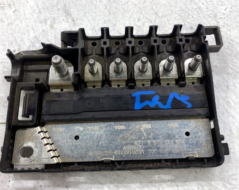
This high-capacity fuse block is installed in the battery cover.
Scheme
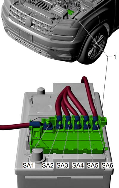
Transcript
| SA1 | 400A generator with voltage regulator |
| SA2 | – |
| SA3 | 100A Radiator Fan |
| SA4 | 80A fuse power supply (on fuse panel C): No. 3, 15, 19, 21, 23, 28, 30, 43, 45, 50 |
| SA5 | Power supply to 125A fuses (on fuse panel C) No. 4, 12, 14, 22, 38, 40, 42, 46, 51, 53. |
| Relay sockets | |
| Power relay terminal 15 | |
| Automatic switch 1 front passenger seat adjustment | |
| Trailer circuit breaker | |
| SA6 | 80A Power steering control module |