Mercedes-Benz Atego 2nd generation was produced in 2004, 2005, 2006, 2007, 2008, 2009, 2010, 2011, 2012. In 2013, 2014, 2015, 2016, 2017 and 2018 – Mercedes Atego 3rd generation. In this material you will find a description of fuses and relays of Mercedes Atego with a block diagram and a photo example of the location. Let’s highlight the cigarette lighter fuse.

Fuse and relay block
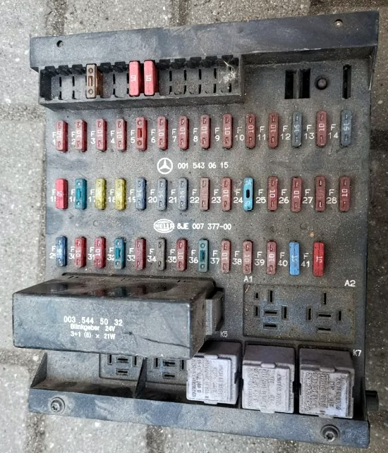
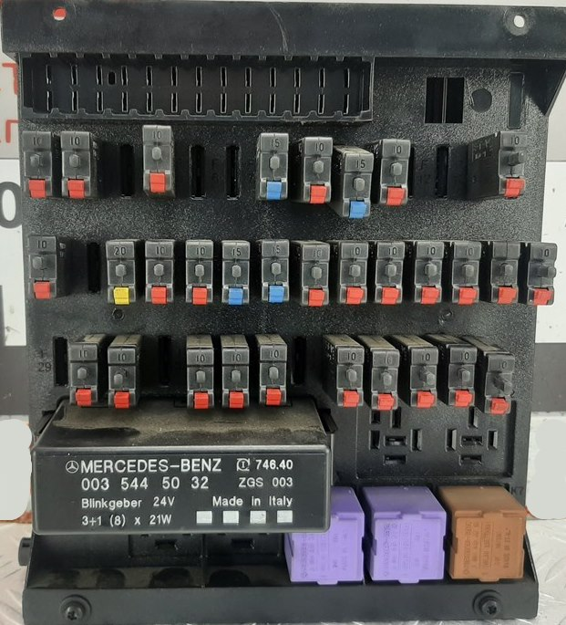
The main fuse and relay block is located at the bottom of the instrument panel on the passenger side behind a protective cover.
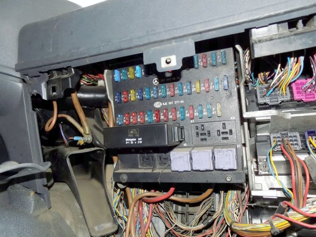
Please note that there is no single general description for the entire generation of tractors. Check the purpose with your diagrams on the back of the protective cover.
Location of block elements
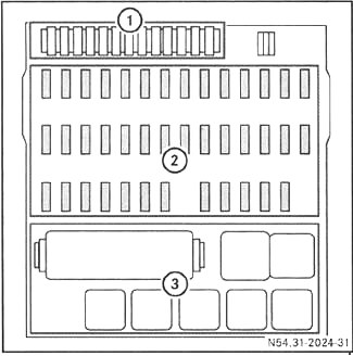
- Spare fuses
- Main fuse compartment
- Relay
Scheme
Description
Fuses
| № | Current | Description |
|---|---|---|
| 1 | 10A | Rear fog lights, including on a trailer |
| 2 | 10A | Instrument cluster lighting/switch illumination, headlight cleaner, headlight range adjustment system, Mounting block – terminal 58 |
| 3 | 10A | Additional turn signals |
| 4 | 10A | Liftgate, 24V radio, handbrake – terminal 30 |
| 5 | 10A | Work light, LSVA (heavy goods vehicle charges) – terminal 30 |
| 6 | 10A | Reserve |
| 7 | 15A | Mounting block – D+ clamp |
| 8 | 10A | Mirror heating system |
| 9 | 15A | 24V power sockets |
| 10 | 10A | Digital tachograph, instrument cluster, diagnostic connector – terminal 30 |
| 11 | 20A | Trailer power socket – terminal 30 |
| 12 | 20A | Trailer ABS power supply socket – clamp 30 |
| 13 | 10A | Interior lighting, Toll Collect system – terminal 30 |
| 14 | 10A | Headlight cleaner |
| 15 | 10A | Three-phase generator, gearbox, LSVA (heavy goods vehicle charges depending on the vehicle’s load capacity) – terminal 15 |
| 16 | 10A | Power take-off mechanisms |
| 17 | 20A | Heater fan, air conditioner |
| 18 | 5A | Instrument cluster, radio, telephone, loudspeaker, fax machine — terminal 15R |
| 19 | 10A | Cigarette lighter |
| 20 | 15A | Switch panel on the front passenger side |
| 21 | 15A | Driver’s door switch panel |
| 22 | 10A | Windshield washer, hazard warning light – clamp 30 |
| 23 | 10A | Low beam right |
| 24 | 10A | Low beam left |
| 25 | 10A | High beam right |
| 26 | 10A | High beam on the left, high beam on indicator light |
| 27 | 10A | Tail light, parking light, left side marker lights, trailer power socket, Toll Collect system |
| 28 | 10A | Tail light, parking light, right side marker lights, trailer power socket |
| 29 | 15A | Transmission control system |
| 30 | 10A | Engine control – terminal 15, vehicles for the transport of dangerous goods (GGVSE): emergency stop switch NOT-AUS |
| 31 | 10A | Switch block on the driver’s door, setting the position of the exterior rear-view mirrors, exhaust gas aftertreatment system block – terminal 15 |
| 32 | 10A | All-wheel drive, ESP® system, additional water heating system |
| 33 | 10A | Windshield washer, hazard warning light, trailer power socket – terminal 15 |
| 34 | 10A | Brake light, reversing light, trailer power socket |
| 35 | 10A | Condensation sensor, trailer ABS power supply socket – terminal 15 |
| 36 | 15A | Additional water heating system |
| 37 | 10A | Windshield washer |
| 38 | 10A | Digital tachograph, instrument cluster, airbag – terminal 15 |
| 39 | 10A | Audible signal, Toll Collect system, diagnostic connector, FleetBoard® system |
| 40 | 10A | Differential lock mechanism |
| 41 | 10A | Seat heating system |
Relay
| № | Description of electrical system components |
|---|---|
| K3 | ABS/BS/EPB disabled |
| K4 | Starter/battery heater relay |
| K5 | D+ |
| K6 | Stop signal |
| K7 | Reverse light |
Additional sections
Scheme
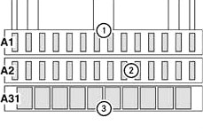
Appointment
A1
| № | Current | Description |
|---|---|---|
| 1 | 10A | Auxiliary heating clock, FleetBoard® system, Toll Collect system – terminal 30 |
| 2 | 20A | Additional heating system |
| 3 | 15A | Central locking system |
| 4 | 15A | Locking system with convenient control |
| 5 | 10A | Electronic brake system, portable lamp power socket – terminal 15 |
| 6 | 15A | 12V power socket |
| 7 | 10A | Voltage transformer 24 V/12 V, 8A/15A Voltage transformer 24 V/12 V, 15A |
| 8 | 10A | Central locking system / convenience locking system, radio remote control, retarder brake |
| 9 | 10A | Compressed air dryer |
| 10 | 15A | Distributor – terminal 30 |
| 11 | 15A | Exhaust gas aftertreatment system unit – terminal 30 |
| 12 | 10A | Hydrofoil |
| 13 | 10A | Transmission control system |
| 14 | 10A | Working light, brake/retarder |
A2
| № | Current | Description |
|---|---|---|
| 1 | 20A | Windshield heating system |
| 2 | 10A | Daytime running lights |
| 3 | 10A | Windshield heating system |
| 4 | 10A | Transmission oil cooling system, cold box / 25A Allison transmission oil cooling system |
| 5 | 15A | Electro-hydraulic autonomous power steering – clamp 30 |
| 6 | 10A | Electro-hydraulic autonomous power steering – clamp 15 |
| 7 | 10A | Additional headlight |
| 8 | 10A | Flashing beacon |
| 9 | 15A | Electronic brake system – terminal 30 |
| 10 | 10A | Telephone/navigation control panel, mobile phone – terminal 30 |
| 11 | 10A | Reserve |
| 12 | 10A | Telephone/navigation control panel, mobile phone – terminal 15 |
| 13 | 20A | Windshield heating system |
| 14 | 15A | Electronic brake system — Terminal 30 |
Individual fuse and relay elements can be installed outside this unit.
Some fuses don’t look like the ones you’re used to seeing in cars, but their functionality is the same. Conventionally, they can all be divided into fuses and automatic ones.
Checking the fuse
- Remove the fuse from the module using pliers and visually inspect it.
- If the fuse wire is blown, replace the faulty fuse with a spare fuse.
- Turn on the electrical consumers and check their operation. If the fuse blows again, contact a specialized workshop with qualified personnel to check the electrical equipment.
Checking the circuit breaker
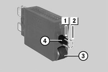
When the circuit breaker trips, the pin (4) moves to the off position (2).
- Remove the circuit breaker from the module.
- Push the pin (4) into the on position (1).
- Press the release button (3).
– If the pin (4) moves to the off position (2), the circuit breaker is OK.
– If the pin (4) does not move to the off position (2), the circuit breaker needs to be replaced. - Press the pin (4) into the on position (1) and reinsert the circuit breaker.
- Turn on the electrical consumers and check their operation. If the circuit breaker trips again, contact a specialized workshop with qualified personnel to check the electrical equipment.