Mercedes-Benz Actros MP4 represents the 4th generation of the Actros model range, which was produced in 2013, 2014, 2015, 2016, 2017, 2018. In this post, we will show a description of the fuses and relays of the Mercedes Actros MP4 with a block diagram and its location. We will note the cigarette lighter fuse.

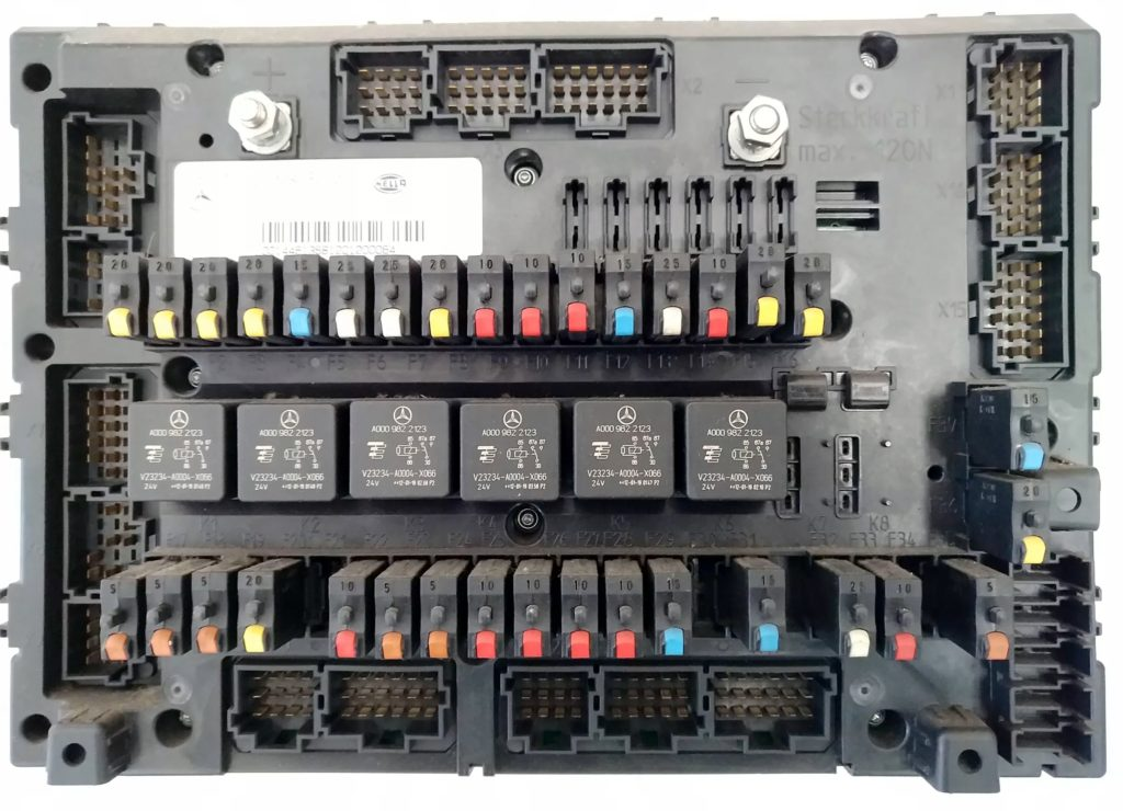
Fuse and relay block
The main fuse and relay block is located in the passenger compartment, at the bottom of the instrument panel on the passenger side.
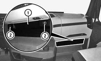
For access, open the latches (2) and remove the cover (1).
The design of the unit and the purpose of the elements in it may differ from the one presented and depends on the year of manufacture and the level of electrical equipment. Check the designations with your diagrams on the back of the protective cover.
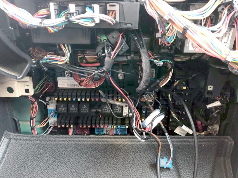
Option 1
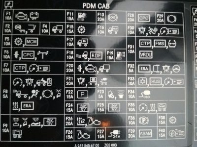
Option 2
Location map
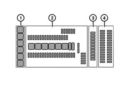
Description
- Relay module A32
- Fuses, relays and diodes in the main module (GM)
- Relay module A31.
- Fuses of modules A1 and A2.
Relay module A32
| № | Description |
|---|---|
| K1 | Windshield heating system |
| K2 | Windshield heating system |
| K3 | Additional headlight – clamp 56a |
| K4 | Reserve |
| K5 | Reserve |
| K6 | Reserve |
Master Module (GM)
SCA
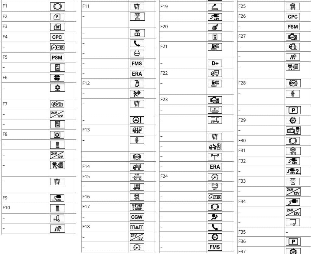
Fuses
| № | Current | Description |
|---|---|---|
| F2 | 20A | Driver’s door control unit |
| F3 | 20A | Front passenger door control unit |
| F4 | 20A | Driving mode control system |
| – | 20A | Tachograph – clamp 30 |
| F5 | 15A | Programmable special module |
| – | 15A | Distributor clamp 30 |
| F6 | 25A | Fan |
| – | 25A | Independent electric air conditioning system |
| F7 | 25A | Radio/navigation system |
| – | 25A | Voltage transformer 12 V |
| – | 25A | Distributor clamp 30 |
| F8 | 20A | Refrigerated box |
| – | 20A | Additional heating system |
| – | 20A | Voltage transformer 12 V |
| – | 20A | Adaptive driving parameter prediction system control unit – terminal 30 |
| – | 20A | LSVA (charges for transporting heavy goods depending on the vehicle’s carrying capacity) |
| F9 | 10A | Diagnostic connector |
| F10 | 10A | Heating system |
| – | 10A | Distance sensor |
| – | 10A | Driver assistance system – clamp 30 |
| F11 | 10A | Toll Collect system |
| – | 10A | Ceiling lights for additional compartment lighting in the rear wall |
| – | 10A | Reading lamp |
| – | 10A | Telephone |
| – | 10A | Tire pressure monitoring system |
| – | 10A | Fleet Management System – Clamp 30 |
| – | 10A | ERA-GLONASS |
| F12 | 15A | Sliding top hatch |
| – | 15A | EDW system (anti-theft alarm system) |
| – | 15A | LSVA (charges for transporting heavy goods depending on the vehicle’s carrying capacity) |
| – | 15A | Steering wheel angle sensor |
| F13 | 25A | Ground clearance adjustment system |
| – | 25A | Hydraulic clutch (retarder turbo clutch) |
| – | 25A | Retarder |
| F14 | 10A | Body manufacturer – clamp 30 |
| F15 | 20A | Trailer |
| – | 20A | Trailer voltage transformer – clamp 30 |
| F16 | 20A | Trailer ABS system – clamp 30 |
| F17 | 5A | Ignition switch |
| – | 5A | Central Internet Gateway |
| F18 | 5A | Modular switch panel |
| – | 5A | Voltage transformer with remote output |
| – | 5A | Instrument combination – clamp 30 |
| F19 | 6A | Cigarette lighter |
| – | 15A | Power socket – terminal 15 |
| F20 | 20A | Seat heating system |
| – | 20A | Distributor clamp 15 |
| F21 | 15A | Fuel pre-filter heating system with water separator |
| – | 15A | Distributor – D+ terminal |
| F22 | 10A | Body manufacturer – D+ clamp |
| – | 10A | Fuel pre-filter heating system with water separator |
| F23 | 5A | BlueTec® exhaust gas aftertreatment system |
| – | 5A | Sunshade |
| – | 5A | Towbar (low-mounted towbar system) |
| – | 5A | Toll Collect system |
| – | 5A | Mounting socket for MEILLER retrofitting |
| – | 5A | Hydraulic Auxiliary Drive (HAD) – Clamp 15 |
| – | 5A | ERA-GLONASS |
| F24 | 5A | Instrument combination |
| – | 5A | Battery disconnector |
| – | 5A | Tachograph |
| – | 5A | Brake system |
| – | 5A | Airbag |
| – | 5A | Telephone |
| – | 5A | Transmission control system |
| – | 5A | Fleet management system |
| – | 5A | Additional headlight |
| F25 | 10A | Trailer ABS system |
| F26 | 10A | Driving mode control system |
| – | 10A | Customizable special module – clamp 15 |
| F27 | 10A | Engine control – terminal 15 |
| – | 10A | Reversing camera |
| – | 10A | Driver assistance system |
| – | 10A | Adaptive driving parameters prediction system control unit – clamp 15 |
| F28 | 10A | Retarder |
| – | 10A | Hydraulic clutch (retarder turbo clutch) |
| – | 10A | Electronic air preparation unit – terminal 15 |
| F29 | 15A | Transmission control system – clamp 30.1 |
| – | 15A | CB radio station |
| F30 | 20A | Brake system – clamp 30.2 |
| F31 | 15A | Trailer brake light |
| F32 | 25A | 24V power sockets |
| – | 25A | Additional 24V power socket |
| F33 | 10A | Ceiling lights for additional roof compartment lighting |
| – | 10A | Voltage transformer with remote output |
| F34 | 25A | 24V high-power power supply socket |
| – | 25A | Voltage transformer 12 V |
| – | 15A | Electrical equipment of the body of another manufacturer |
| F35 | Reserve | |
| F36 | 20A | Electronic air preparation unit – terminal 30 |
| F37 | 15A | Transmission control system – clamp 30.2 |
Relay
| № | Description |
|---|---|
| K1 | Gain – clamp 15 |
| K2 | Gain – D+ terminal |
| K3 | Gain – clamp 15 |
| K4 | Gearbox oil cooling |
| K5 | Gain – clamp 15 |
| K6 | Trailer brake light |
| K7 | Bistable relay |
| K8 | Bistable relay |
| K9 | Reserve |
SSAM
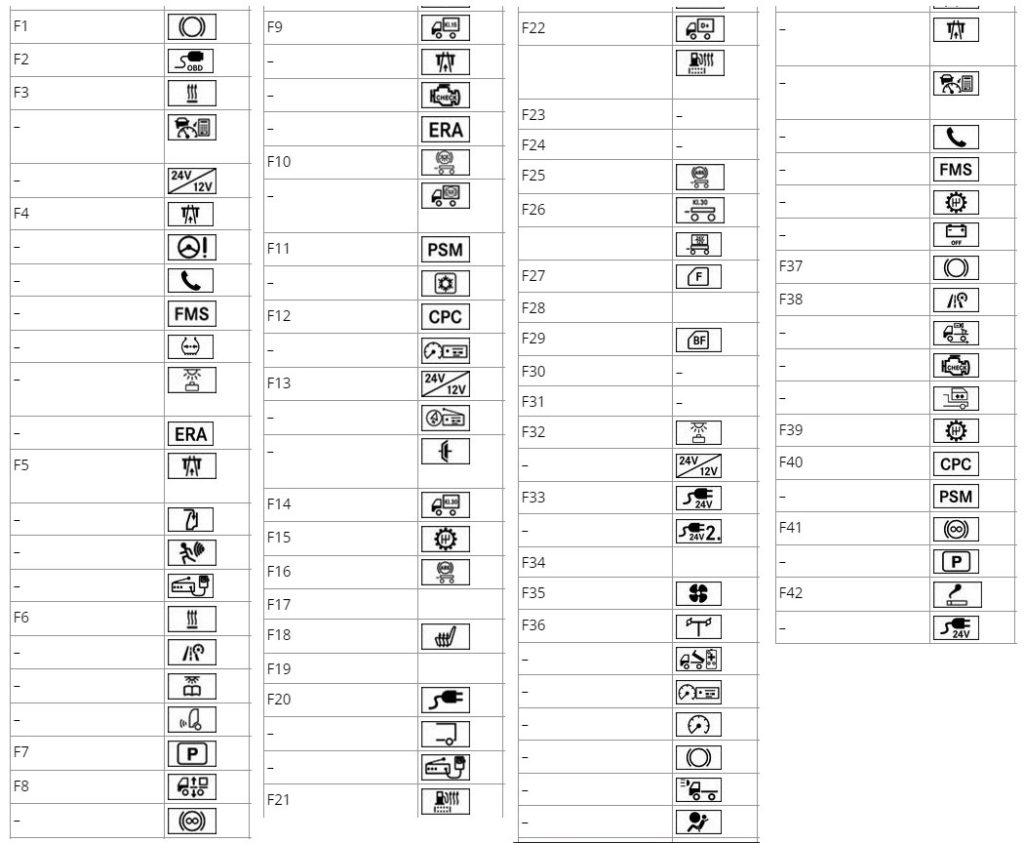
Fuses
| № | Current | Description |
|---|---|---|
| F1 | 20A | Brake system – clamp 30.1 |
| F2 | 10A | Diagnostic connector |
| F3 | 15A | Additional heating system |
| – | 15A | Adaptive driving parameter prediction system control unit |
| – | 15A | Voltage transformer 12 V |
| F4 | 10A | Toll Collect system |
| – | 10A | Steering wheel angle sensor |
| – | 10A | Telephone |
| – | 10A | Fleet management system |
| – | 10A | Tire pressure monitoring system |
| – | 10A | Ceiling lights for additional compartment lighting in the rear of the vehicle – clip 30 |
| – | 10A | ERA-GLONASS |
| F5 | 15A | LSVA (charges for transporting heavy goods depending on the vehicle’s carrying capacity) |
| – | 15A | Sliding top hatch |
| – | 15A | EDW system (anti-theft alarm system) |
| – | 15A | CB radio station |
| F6 | 10A | Heating system |
| – | 10A | Driver assistance system |
| – | 10A | Reading lamp – clamp 30 |
| – | 10A | Distance sensor |
| F7 | 20A | Electronic air preparation unit – terminal 30 |
| F8 | 25A | Ground clearance adjustment system |
| – | 25A | Retarder |
| F9 | 10A | Body manufacturer – clamp 15 |
| – | 10A | Toll Collect system |
| – | 10A | BlueTec® exhaust gas aftertreatment system |
| – | 10A | ERA-GLONASS |
| F10 | 20A | Trailer brake light |
| – | 20A | Body manufacturer installed brake light |
| F11 | 20A | Programmable special module |
| – | 20A | Cooler box – clamp 30 |
| F12 | 20A | Driving mode control system |
| – | 20A | Tachograph – clamp 30 |
| F13 | 25A | Voltage transformer 12 V |
| – | 25A | Radio/navigation system – clamp 30 |
| – | 25A | Hydraulic clutch (retarder turbo clutch) |
| F14 | 10A | Body manufacturer – clamp30 |
| F15 | 15A | Transmission control system – clamp 30.1 |
| F16 | 10A | Trailer ABS system |
| F17 | Reserve | |
| F18 | 15A | Seat heating system |
| F19 | Reserve | |
| F20 | 25A | 24V high-power power supply socket |
| – | 15A | Electrical equipment of the body of another manufacturer |
| – | 15A | CB radio station |
| F21 | 15A | Fuel pre-filter heating system with water separator |
| – | 15A | Distributor – D+ terminal |
| F22 | 10A | Body manufacturer – D+ clamp |
| 10A | Fuel pre-filter heating system with water separator | |
| F23 | Reserve | |
| F24 | Reserve | |
| F25 | 20A | Trailer ABS system |
| F26 | 20A | Trailer |
| 20A | Trailer voltage transformer – clamp 30 | |
| F27 | 20A | Driver’s door control unit |
| F28 | Reserve | |
| F29 | 20A | Front passenger door control unit |
| F30 | Reserve | |
| F31 | Reserve | |
| F32 | 10A | Ceiling lights for additional roof compartment lighting |
| – | Voltage transformer with remote output | |
| F33 | 25A | 24V power sockets |
| – | 25A | Additional 24V power socket |
| F34 | Reserve | |
| F35 | 25A | Fan |
| F36 | 5A | Hydraulic Auxiliary Drive (HAD) |
| – | 5A | Mounting socket for MEILLER retrofitting |
| – | 5A | Tachograph |
| – | 5A | Instrument combination |
| – | 5A | Brake system |
| – | 5A | Additional headlight |
| – | 5A | Airbag |
| – | 5A | LSVA (charges for transporting heavy goods depending on the vehicle’s carrying capacity) |
| – | 5A | Adaptive driving parameter prediction system control unit |
| – | 5A | Telephone |
| – | 5A | Fleet management system |
| – | 5A | Transmission control system |
| – | 5A | Battery disconnector – clamp 15 |
| F37 | 20A | Brake system – clamp 30.2 |
| F38 | 10A | Driver assistance system |
| – | 10A | Reversing camera |
| – | 10A | Engine control – terminal 15 |
| – | 10A | Swap body – clamp 15 |
| F39 | 15A | Transmission control system – clamp 30.2 |
| F40 | 10A | Driving mode control system |
| – | 10A | Customizable special module – clamp 15 |
| F41 | 10A | Retarder |
| – | 10A | Electronic air preparation unit – terminal 15 |
| F42 | 5A | Cigarette lighter |
| – | 15A | Power socket |
Relay
| № | Description |
|---|---|
| K1 | Reserve |
| K2 | Gain – D+ terminal |
| K3 | Gearbox oil cooling |
| K4 | Gain – clamp 15 |
| K5 | Gain – clamp 15 |
| K6 | Trailer brake light |
| K7 | Gain – clamp 15 |
| K8 | Bistable relay |
| K9 | Bistable relay |
Relay module A31
Scheme
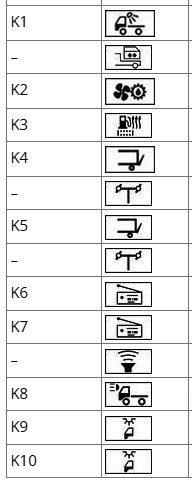
Transcript
| K1 | Working light |
| – | Swap body |
| K2 | Oil cooling of the transfer case |
| K3 | Fuel pre-filter heating system with water separator |
| K4 | Tail lift |
| – | Disabling the auxiliary hydraulic drive (HAD) |
| K5 | Tail lift |
| – | Disabling the auxiliary hydraulic drive (HAD) |
| K6 | 12V radio receiver – terminal 58 |
| K7 | 12V radio receiver – 15R clamp |
| – | Subwoofer |
| K8 | Additional headlight – clip 58 |
| K9 | Interior lighting with a low roof |
| K10 | Interior lighting with a low roof |
Modules A1 and A2
Scheme
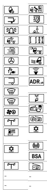
Appointment
| № | Current | Description |
|---|---|---|
| A1 | ||
| F1 | 5A | Cabin tilt pump |
| F2 | 10A | Tail lift |
| F3 | 10A | Flashing beacon |
| F4 | 10A | Working light |
| – | 10A | Swap body |
| F5 | 10A | Illuminated Mercedes-Benz triangular star |
| – | 10A | Portable lamp power socket |
| F6 | 15A | Electrical equipment of the body of another manufacturer |
| F7 | 25A | Windshield heating system |
| F8 | 25A | Windshield heating system |
| F9 | 10A | Oil cooling of the transfer case |
| – | 10A | Hydraulic Auxiliary Drive (HAD) |
| F10 | 15A | Fuel pre-filter heating system with water separator |
| F11 | 20A | Independent electric air conditioning system |
| F12 | 15A | Hydraulic Auxiliary Drive (HAD) |
| F13 | Reserve | |
| F14 | Reserve | |
| A2 | ||
| F1 | 10A | Mounting socket for MEILLER retrofitting |
| F2 | 20A | Electrical equipment of the body of another manufacturer 2 and 3 |
| – | 20A | Body additional axle switch |
| F3 | 10A | Controlled auxiliary bridge |
| F4 | 15A | Additional headlight |
| F5 | 10A | Air supply control system |
| F6 | 10A | Subwoofer |
| F7 | 5A | Equipment in accordance with the regulations for the transport of dangerous goods by road, for England |
| F8 | 5A | Interior lighting with a low roof |
| F9 | 5A | CB radio station |
| F10 | 15A | Radio/navigation system |
| F11 | 5A | Independent electric air conditioning system |
| – | 5A | Antenna amplifier |
| – | 5A | Cornering assistant |
| F12 | 10A | 12V radio receiver |
| F13 | Reserve | |
| F14 | Reserve | |
Checking the fuses
Some fuses don’t look like the ones you’re used to seeing in cars, but their functionality is the same. Conventionally, they can all be divided into fuses and automatic ones.
Checking the fuse
- Remove the fuse from the module using pliers and visually inspect it.
- If the fuse wire is blown, replace the faulty fuse with a spare fuse.
- Turn on the electrical consumers and check their operation. If the fuse blows again, contact a specialized workshop with qualified personnel to check the electrical equipment.
Checking the circuit breaker
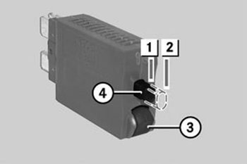
When the circuit breaker trips, the pin (4) moves to the off position (2).
- Remove the circuit breaker from the module.
- Push the pin (4) into the on position (1).
- Press the release button (3).
– If the pin (4) moves to the off position (2), the circuit breaker is OK.
– If the pin (4) does not move to the off position (2), the circuit breaker needs to be replaced. - Press the pin (4) into the on position (1) and reinsert the circuit breaker.
- Turn on the electrical consumers and check their operation. If the circuit breaker trips again, contact a specialized workshop with qualified personnel to check the electrical equipment