Mercedes ML W166 represents the third generation of M-class SUVs Mercedes-Benz which was produced in 2012, 2013, 2014, 2015, 2016, 2017, 2018, 2019, 2020 and was supplied all over the world. During this time, the model was restyled. This information will also be useful for owners of Mercedes GL X166 and Mercedes GLS X166 , since these cars have similar electrical circuits. In it you can find a description of the fuses and relays Mercedes 166 with block diagrams, photo examples of their execution and locations. Note the fuse responsible for the cigarette lighter.

The purpose of the fuses and relays in the blocks may differ from that shown and depends on the year of manufacture, equipment level and region of delivery of your vehicle.
Blocks under the hood
Location
Scheme
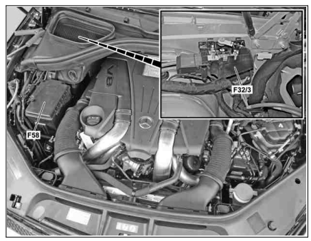
Description
- F32/3 – Power fuse box
- F58 – Fuse and Relay Box
Fuse and relay box
Photo – example
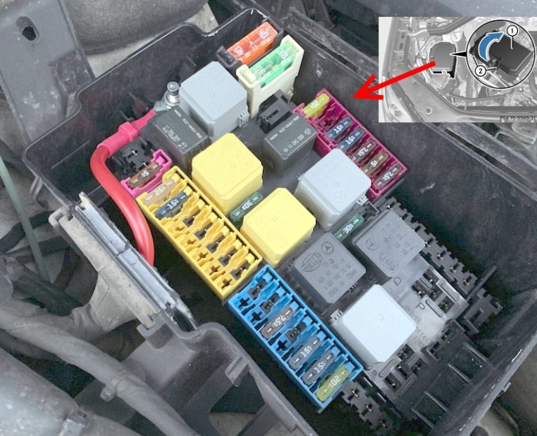
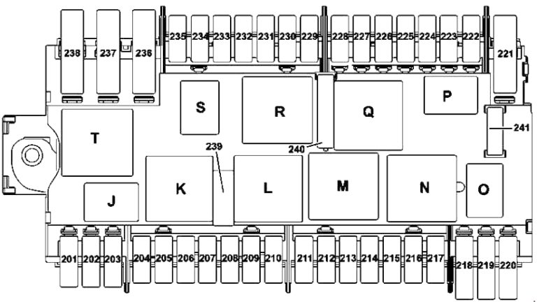
Designation
| 201 | Reserve |
| 202 | 20A Heating device of independent heater |
| 203 | 5A Alarm Siren |
| 204 | 25A Electronic stability control unit |
| 205 | 15A Left horn |
| Right horn | |
| 206 | Reserve |
| 207 | Reserve |
| 208 | Reserve |
| 209 | Reserve |
| 210 | Reserve |
| 211 | Reserve |
| 212 | Reserve |
| 213 | 7.5A Valid for motors 642, 651: |
| CDI control unit | |
| Valid for engine 157, 276, 278: | |
| ME control unit | |
| 214 | 15A Valid for engine 157, 276, 278: |
| ME control unit | |
| Valid for vehicles with 651 engine: | |
| CDI control unit | |
| BlueTEC: | |
| Nox sensor control unit | |
| 215 | 15A Valid for vehicles with engine 157, 276, 278: |
| Electrical plug connection engine/engine compartment (terminal 7) | |
| Valid for vehicles with engine 642: | |
| Electrical plug connection engine/engine compartment (terminal 7) via cable end sleeve terminal 87 D3 | |
| Radiator shutter actuator | |
| Valid for vehicles with 651 engine: | |
| Electrical plug connection engine/engine compartment (terminal 7) | |
| Radiator shutter actuator | |
| 216 | 15A Valid for engine 157, 276, 278: |
| Cable termination joint, terminal 87D2 | |
| Valid for vehicles with engine 642: | |
| CDI control unit | |
| Electrical plug connection engine/engine compartment (terminal 6) | |
| Adjustable left engine mount | |
| Adjustable right engine mount | |
| Valid for vehicles with 651 engine: | |
| Fan motor | |
| CDI control unit | |
| Electrical plug connection engine/engine compartment (terminal 6) | |
| Adjustable left engine mount (Y123) Adjustable right engine mount | |
| 217 | 20A Valid for engine 157, 276, 278: |
| Electrical plug connection engine/engine compartment (terminal 5) | |
| Valid for engines 642, 651: | |
| CDI control unit | |
| Electrical plug connection engine/engine compartment (terminal 5) | |
| 218 | Reserve |
| 219 | 10A Valid for engine 278, 157: Charge air cooler circulation pump |
| 220 | Reserve |
| 222 | Reserve |
| 223 | Reserve |
| 224 | Reserve |
| 225 | Reserve |
| 226 | Reserve |
| 227 | Reserve |
| 228 | Reserve |
| 229 | 7.5A Front Left Headlight |
| 230 | 5A Electronic stability control unit |
| 231 | 7.5A Front Right Headlight |
| 232 | 15A Control unit for fully integrated gearbox control system |
| Vehicles without “ECO Start-Stop” function: Control unit for additional transmission oil pump | |
| 233 | 15A Headlight Control Unit |
| 234 | 5A Electrical control module DISTRONIC |
| 235 | 20A Windscreen wiper heating |
| 236 | Reserve |
| 237 | 15A KP 722.9: Automatic transmission servo drive module for DIRECT SELECT system |
| 238 | 40A AIRMATIC Compressor |
| 239 | 30A Windscreen Wiper Motor |
| 240a | 30A Vehicles without “ECO Start-Stop” function: Starter |
| 240b | 30A Vehicles with “ECO Start-Stop” function: Engine compartment power fuse box |
| 241 | Reserve |
| Relay | |
| J | Sound signal relay |
| K | Windscreen wiper mode relay 1/2 |
| L | Windscreen wiper relay on/off |
| M | Starter terminal 50 relay |
| N | Relay electric circuit terminals 87M |
| THE | Turbocharger relay |
| P | Reserve relay |
| Q | Relay terminal 15 (without support) |
| R | Relay terminal 15 |
| S | Windscreen wiper heating relay |
| T | AIRMATIC relay |
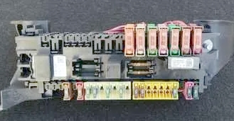
Power fuse box
Photo
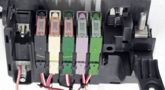
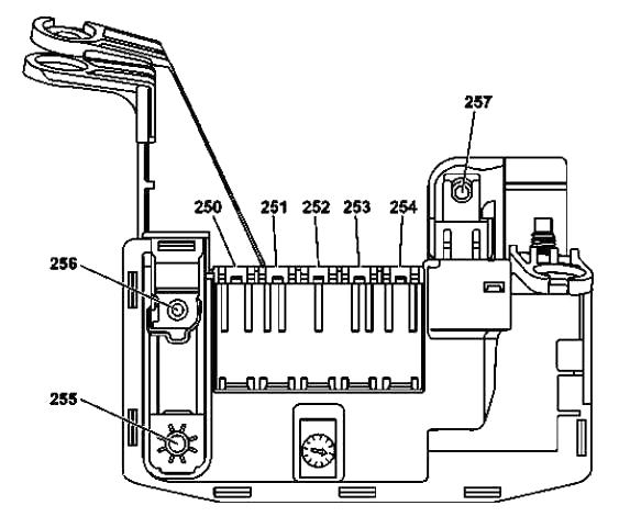
Transcript
| 250 | 40A SAM Control Unit |
| 251 | 40A SAM Control Unit |
| 252 | 40A SAM Control Unit |
| 253 | 30A Front Left Door Control Unit |
| 254 | 30A Rear Left Door Control Unit |
| 255 | 200A Battery Compartment Power Fuse Block |
| 256 | 150A Rear Passenger Compartment Fuse Box |
| 257 | 150A Diesel Engine: Additional Electric Heater |
It is possible to install some relay elements outside of these blocks, for example, a relay for heating the hoses to the washer nozzles.
Blocks in the cabin
Location
Scheme
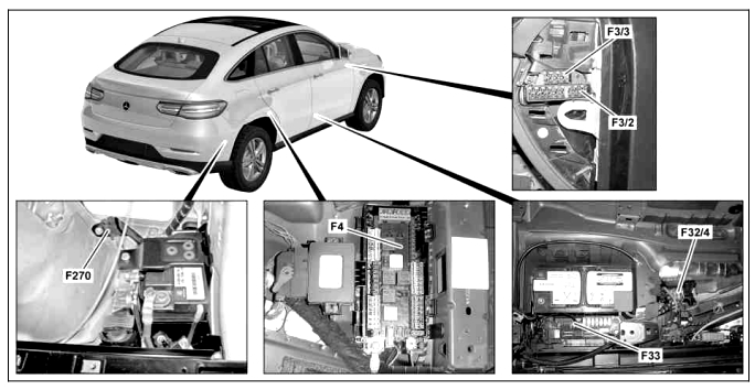
Purpose
- F3/2, F3/3 – Fuse box in the instrument panel
- F4 – Main fuse and relay box in the rear of the passenger compartment
- F32/4 – Power fuse box
- F33 – Battery compartment fuse box
- F270 – Buffer battery fuse
Fuse and relay box
The main block with fuses and relays in the passenger compartment is located under the rear seat and is covered with a protective cover.
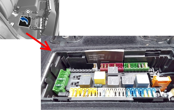
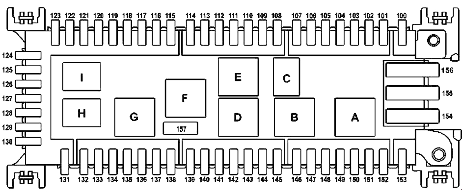
Description
| 100 | 5A Audio module |
| COMAND control module | |
| External navigation electrical plug connection | |
| 101 | 20A Trailer Recognition Control Unit |
| 102 | 7.5A Driver Seat Control Unit |
| 103 | 7.5A Front Passenger Seat Control Unit |
| 104 | 5A Mobile Antenna Amplifier/Compensator |
| Bluetooth® Module | |
| 105 | 5A Holder for navigation module |
| 106 | 5A Tailgate Drive Control Unit |
| 107 | 10A 2nd Row Left Seat Release Module |
| 2nd row seat release module right | |
| 108 | Reserve |
| 109 | Reserve |
| 110 | 5A AdBlue® Control Unit |
| 111 | 15A Trailer Socket |
| 112 | 5A Fuel Pump Control Unit |
| 113 | 5A Electric Parking Brake Control Unit |
| 114 | 5A Outdoor Lighting Switch |
| 115 | 5A Trailer Recognition Control Unit |
| 116 | 5A Radar Sensor Control Unit Terminal 87 Termination Sleeve |
| COLLISION PREVENTION ASSIST control module | |
| 117 | 5A Night Vision Control Unit |
| 118 | Reserve |
| 119 | 5A Transfer Case Control Unit |
| 120 | 5A Fuel quality sensor |
| Digital tachograph control unit | |
| 121 | Reserve |
| 122 | Reserve |
| 123 | Reserve |
| 124 | 30A Electrical plug connection for Elektric Brake Control function |
| 125 | Reserve |
| 126 | 15A Trailer Recognition Control Unit |
| 127 | 30A Driver Seat Control Unit |
| 128 | 20A Trailer Recognition Control Unit |
| 129 | 30A Front Passenger Seat Control Module |
| 130 | 20A Trailer Recognition Control Unit |
| 131 | Reserve |
| 132 | 25A Fuel Pump Control Unit |
| 133 | 5A Receiver for remote control of independent heater |
| 134 | 5A Seat occupied recognition system pressure sensor |
| Front passenger seat occupancy recognition system and AKSE | |
| 135 | 5A Glove box light |
| 136 | 7.5A Supplemental Restraint System Control Unit |
| 137 | 5A Electrical Fuse Preparatory for Installation of Electronic Toll Collection System |
| Electronic equipment rear view camera | |
| External navigation electrical plug connection | |
| 138 | 15A Active Roll Stabilization Control Unit |
| 139 | Reserve |
| 140 | 7.5A AdBlue® Control Unit |
| 141 | 15A AdBlue® Control Unit |
| 142 | 20A AdBlue® Control Unit |
| 143 | Reserve |
| 144 | Reserve |
| 145 | 7.5A Cup Holder |
| 146 | 30A Rear Window Rejector Filter |
| 147 | 30A Audio module |
| COMAND control module | |
| 148 | 15A Cigarette Lighter Heating Element |
| Detachable cup holder connection | |
| 149 | 5A 115V Socket |
| 150 | 20A Socket in the trunk |
| 151 | 20A Socket 2nd row seats left |
| Power outlet in the 2nd row of seats on the right | |
| 152 | 30A Rear compartment systems control unit |
| 153 | 25A AC/DC Converter Control Unit |
| 154 | 40A Tailgate Drive Control Unit |
| 155 | Reserve |
| 156 | Reserve |
| 157 | 15A Tailgate Windscreen Wiper Motor |
| Relay | |
| A | Relay socket terminals 15R2 |
| B | Rear window heating relay |
| C | Backup relay |
| D | AdBlue ® relay |
| AND | Relay terminal 15 |
| F | Rear Window Wiper Relay |
| G | Relay terminals 15R1 |
| H | Backup relay |
| I | Backup relay |
Fuses 148–151 are responsible for the cigarette lighter.
Fuse box in the panel
At the right end of the instrument panel, behind the protective cover, there is a fuse box.
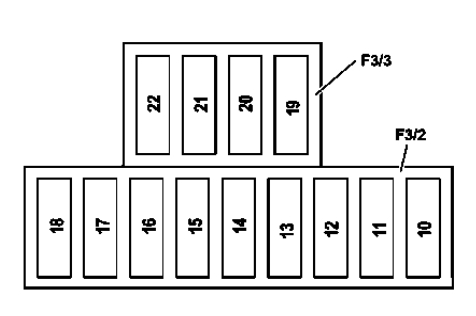
Designation
| 10 | 7.5A | Electronic ignition switch control unit |
| 11 | 10A | Electronic Steering Column Module Control Unit |
| 12 | 5A | Instrument cluster |
| 13 | 15A | Electronic auxiliary fan controller |
| 14 | 5A | Diagnostic connector |
| 15 | 5A | Upper control panel |
| 16 | Reserve | |
| 17 | Reserve | |
| 18 | Reserve | |
| 19 | 15A | Climate control system control panel |
| 20 | 5A | Electronic Steering Column Module Control Unit |
| 21 | 7.5A | Display Audio/COMAND |
| 22 | Reserve |
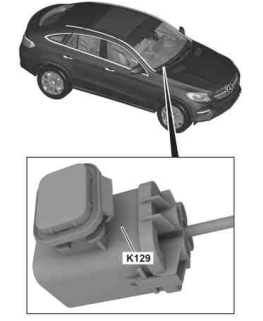
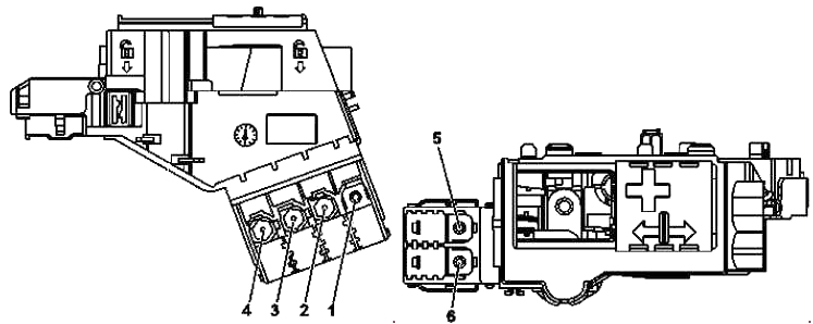
Fuse box near the battery
Another block of fuses is installed in the niche next to the battery.
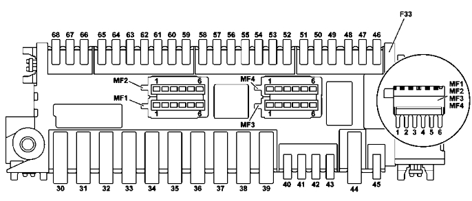
Purpose
| 30 | 40A Speaker Amplifier Control Unit |
| 30A Woofer Amplifier | |
| 31 | 40A Engine Compartment Fuse and Relay Module |
| 32 | 40A Fan Controller |
| 33 | 40A Front Left Reversible Seat Belt Tensioner |
| 34 | 40A Rear Fuse Box |
| 35 | 40A Front Right Reversible Seat Belt Tensioner |
| 36 | 40A Fuse Box Terminal 30 Front Panel |
| 37 | 40A Test Lead |
| 38 | Reserve |
| 39 | Reserve |
| 40 | 25A Electronic control of the rear air conditioning fan |
| 41 | Reserve |
| 42 | Reserve |
| 43 | Reserve |
| 44 | Reserve |
| 45 | 5A Digital tachograph control unit |
| 46 | Reserve |
| 47 | 10A Speaker Amplifier Control Unit |
| 48 | 30A Rear compartment systems control unit |
| 49 | 5A EDW/Towaway/Interior Security Control Unit |
| 50 | 5A Emergency Call System Control Unit |
| 51 | 5A Antenna amplifier FM 1, AM, ZV and KEYLESS-GO |
| 52 | 30A Front Right Door Control Unit |
| 53 | 15A Ceiling Control Panel |
| 54 | Measuring wire |
| 55 | 30A Rear compartment systems control unit |
| 56 | 15A Keyless-Go Control Unit |
| 57 | 30A Rear Right Door Control Unit |
| 58 | 30A Transfer Case Control Unit |
| 59 | 7.5A Supplemental Restraint System Control Unit |
| 60 | 7.5A Ceiling Control Panel |
| 61 | Reserve |
| 62 | 15A AIRMATIC control unit |
| 63 | 20A Panoramic Sliding Sunroof Control Module |
| Sliding Sunroof Control Module | |
| 64 | 30A Multi-contour seat air pump |
| 65 | 30A Fuse Box, Terminal 30g, Front Panel |
| 66 | Reserve |
| 67 | 30A Electric Parking Brake Control Unit |
| 68 | 30A Electric Parking Brake Control Unit |
| MF1 | 5A Pin 1: Audio module/COMAND system control panel |
| Contact 2: | |
| Lower control panel | |
| Off-road driving mode control panel | |
| Contact 3: Parking assistance control unit | |
| Contact 4: Electronic stability control unit | |
| Contact 5: SAM Control Unit | |
| Contact 6: Speaker Amplifier Control Unit | |
| MF2 | 5A Contact 1: HBF Control Unit |
| Contact 2: Tire pressure monitoring system control unit | |
| Contact 3: | |
| Digital Sound Broadcasting Control Unit | |
| Satellite Digital Audio Radio (SDAR) Control Unit | |
| Contact 4: Multifunctional camera | |
| Contact 5: Multimedia Interface Control Unit | |
| Contact 6: | |
| Rear view camera | |
| 360° Camera Control Unit | |
| MF3 | 5A Contact 1: Rear left display |
| Contact 2: Display in the rear compartment on the right | |
| Contact 3: | |
| TV tuner (analog/digital) | |
| Digital TV tuner | |
| Contact 4: DVD Player | |
| Contact 5: Video and radar sensor control unit | |
| Contact 6: Reserve | |
| MF4 | Contact 1: Reserve |
| Contact 2: Reserve | |
| Contact 3: Reserve | |
| Contact 4: Reserve | |
| Contact 5: Reserve | |
| Contact 6: Reserve |
Power fuse box
This high power fuse block is also located near the battery.
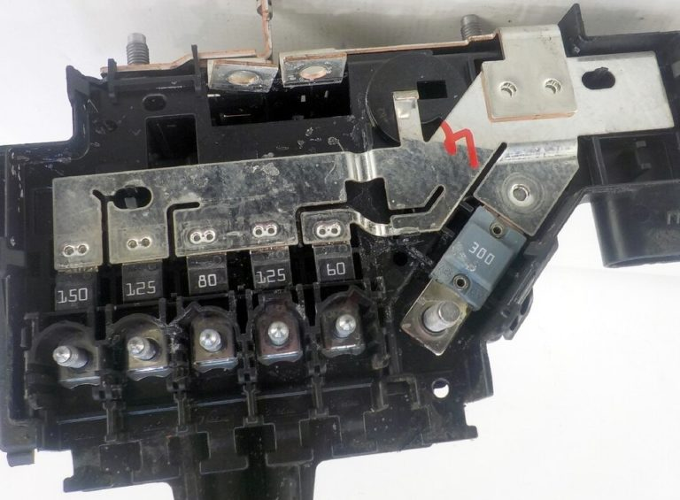
Transcript
| 1 | 40A | Electronic stability control unit |
| 2 | Reserve | |
| 3 | 30A | Vehicles with “ECO Start-Stop” function: Engine compartment fuse and relay module |
| 4 | Reserve | |
| 5 | 150A | Engine Compartment Fuse and Relay Module |
| 6 | 125A | Fan motor |
| 7 | 300/400A | Passenger compartment fuse box |
| 8 | 100A | Electric Power Steering Control Unit |