Audi A1 (body code – 8X) – subcompact car, went on sale went on sale in September 2010. It is still being produced. In 2011, sales of the Audi A1 e-tron electric car with a range of 50 km began. Our material provides information on the locations and descriptions of the fuses and relays of the Audi A1. The placement of the blocks is also relevant for the 5-door car and the Sportback version.
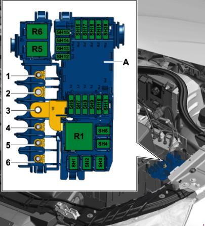
Block locations
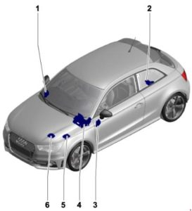
- Fuse block D-SD-;
- Fuse block A-SA-;
- Fuse block C-SC-;
- Relay/fuse bracket F-SF-;
- Fuse block B-SB-, fuse block H-SH-;
- Fuse block B-SB-.
Please note that the diagram may change depending on the equipment and year of manufacture of the car! Check the description on the back of the protective cover.
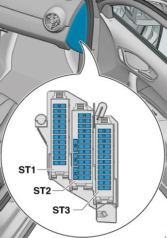
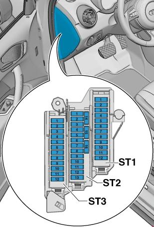
Fuse block – No. 1
Scheme
Description of the scheme
ST1 panel (black color)
| 1 | 7,5 | Control unit for electric steering column lock -J764- |
| 2 | 20 | Trailer recognition control unit -J345- |
| 3 | 20 | Trailer recognition control unit -J345- |
| 4 | 30 7,5 | Mechatronics for dual clutch transmission -J743- , until October 2014 Electronic damping control unit -J250- , from January 2014 |
| 5 | 30 | Headlight washer relay -J39- Headlight washer pump -V11- |
| 6 | 5 | Vehicle location system interface control unit -J843- |
| 7 | 7,5 | Control unit for access control and engine start system -J518- |
| 8 | 15 | Mechatronics for dual clutch transmission -J743- , up to October 2014 |
| 9 | 20 | Sliding sunroof motor -V1- |
| 10 | 7,5 | Selector sensor control unit -J587- |
| 11 | 15 | Engine electronic power supply relay -J757- , up to October 2014 Fuel pressure control valve -N276- , up to October 2014 |
| 12 | – | Not used |
ST2 panel (brown color)
| 1 | 5 | Reversing light switch -F4- Selector switch sensor control unit -J587- Mechatronics for dual clutch transmission -J743- |
| 2 | 10 | High pressure sensor -G65- Engine oil level and temperature sensor -G266- Air conditioning control unit -J301- Socket relay -J807- Auto-dimming interior rearview mirror -Y7- Connector, 16-pin -T16- , diagnostic connector |
| 3 | 5 | Data bus diagnostic interface -J533- |
| 4 | 5 | Heater control unit -J65- Body noise control unit -J869- |
| 5 | 7,5 | Light switch -E1- Starter relay 1 -J906- Voltage stabilizer -J532- Starter relay 2 -J907- Auto-dimming interior rearview mirror relay -J910- Left front headlight -MX1- Right front headlight -MX2- |
| 6 | 5 | Light switch -E1- |
| 7 | 5 | ABS control unit -J104- , until October 2014 Voltage stabilizer 2 -J570- , until October 2014 Electronic damping control system control unit -J250- , from January 2014 |
| 8 | 5 | Driver’s seat heating control -E94- Front passenger seat heating control -E95- Hazard warning light button -E229- Rear window heating switch -E230- ASR and ESP button -E256- Parking assist button – Start-stop button -E693- Trailer recognition control unit -J345- Left injector heating resistor -Z20- Right injector heating resistor -Z21- |
| 9 | 5 | Power steering control unit -J500- |
| 10 | 5 7,5 | Air flow meter -G70- Fuel pump control unit -J538- Crankcase ventilation heater -N79- |
| 11 | 5 | Airbag control unit -J234- Front passenger airbag warning light off -K145- |
| 12 | 5 | Parking assistant control unit -J446- |
| 13 | 5 | Headlight leveling control unit -J431- |
| 14 | 30 | Seat heating control unit -J882- |
| 15 | 15 | Rear wiper motor -V12- |
| 16 | 5 | Engine control unit -J623- Air flow meter -G70- |
ST3 panel (red color)
- Not used
- Not used
- 5-10A – All-wheel drive control unit -J492-, gradual output
- Not used
- Not used
- Not used
- Not used
- Not used
- Not used
- 5-10A-Control unit for special vehicles -J608-
- Not used
- Not used
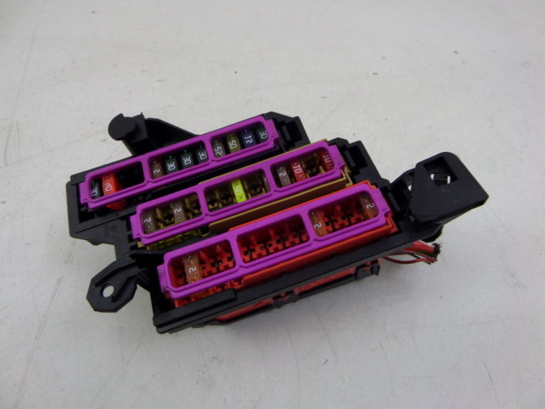
Block photo
Fuse block – No. 2
The unit is located on the positive pole of the battery (only for vehicles with a battery in the luggage compartment) .
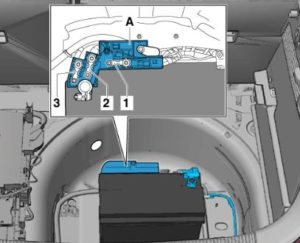
Transcript
- Not used;
- On-board network power supply / Power supply of engine components;
- Not used;
- Battery disconnection fuse-N253-.
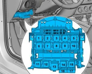
Fuse block – No. 3
Scheme
ST1 panel (black color)
| 1 | 30 | Digital audio system control unit -J525- Voltage stabilizer -J532- Radio -R- |
| 2 | 40 | Heater control unit -J65- Contact relief relay X -J59- Supply air fan control unit -J126- Supply air fan -V2- |
| 3 | 20 | Cigarette lighter -U1- 12 V socket -U5- |
| 4 | 15 | Trailer recognition control unit -J345- |
| 5 | 5 | Data bus diagnostic interface -J533- |
| 6 | 30 | Front passenger door control unit -J387- Rear right door control unit -J389- |
| 7 | 30 | Driver’s door control unit -J386- Rear left door control unit -J388- |
| 8 | 30 | Rear window heating relay -J9- Rear window heating -Z1- |
| 9 | 25 | ABS control unit -J104- |
| 10 | 20 | Onboard power supply control unit -J519- |
| 11 | 15 | High-frequency horn -H2- Low-frequency horn -H7- Horn relay -J413- |
| 12 | 30 | Onboard power supply control unit -J519- |
Fuse number 3 at 20A is responsible for the cigarette lighter.
ST2 panel (brown color)
| 1 | 5 | Anti-theft alarm buzzer -H12- Anti-theft system sensor -G578- |
| 2 | 5 5 7,5 | Terminal 30 power supply relay -J317- ( 22) Motronic power supply relay -J271- (21) Engine control unit -J623- |
| 3 | 5 | Onboard power supply control unit -J519- |
| 4 | 515 | ABS control unit -J104- Voltage stabilizer 2 -J570- All-wheel drive control unit -J492- |
| 5 | – | Not used |
| 6 | 5 | Rain and light sensor -G397- Mobile phone amplifier -R86- Phone holder -R126- Front module for ceilings -WX3- |
| 7 | 15 20 | Fuel pump control unit -J538- Fuel pump relay -J17- ( 22) |
| 8 | 10 | Relay for additional cooling system pump -J496- , up to October 2014 |
| 9 | 5 | Steering column control unit -J527- |
| 10 | 5 | Light switch -E1- |
| 11 | 10 | Climatronic control unit -J255- Air conditioning control unit -J301- Front passenger door control unit -J387- (until April 2012) Rear right door control unit -J389- (until April 2012) Plug connector, 16-pin – T16-, diagnostic connector |
| 12 | 10 | Driver’s door control unit -J386- (until April 2012) Rear left door control unit -J388- (until April 2012) |
| 13 | 10 | Onboard power supply control unit -J519- |
| 14 | 20 | Socket relay -J807- only for vehicles without TSU socket |
| 15 | 30 | Onboard power supply control unit -J519- |
| 16 | 20 | Wiper motor 1 switching relay -J368- , up to October 2014 Engine component supply relay -J757- Ignition coils 1 with output stage -N70- |
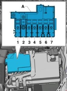
Relay bracket – No. 4
Marking
1-40-Voltage stabilizer -J532-
2-50-Supply fuse block 1 -ST1- on fuse block D -SD-
3-40-Power supply relay terminal 15 -J329-
4-40-ABS control unit -J104-
5-5-Voltage stabilizer 2 -J570-, gradual output
6-5-Onboard power supply control unit -J519-, Voltage stabilizer -J532-
16-10-Brake light switch -F- (from November 2011 to October 2014) / clutch pedal position sensor -G476- (from November 2011 to October 2014)
17-5-Heating element of the lambda probe -Z19- (from November 2011 to October 2014)
Fuse block – No. 5
Decoding the scheme
- 175A – Alternator -C-
- 40A – Low-power heating relay -J359- / Air heater element -Z35-
- 110A – On-board power supply / Engine component power supply
- 80A – Power steering control unit -J500-
- 50A/40A – Coolant fan thermal switch -F18- / Radiator fan control unit -J293-
- 50A – Glow plug control unit -J179-
- 60A – High-power heating relay -J360- / Battery monitoring control unit
Fuse block – No. 6
Transcript
| 1 | 110/50A Onboard power supply, Engine component power supply, Radiator fan control unit -J293, Radiator fan -V7- |
| 2 | 250A Alternator -C-, Voltage regulator -C1- |
| 3 | AKB + |
| 4 | 80A Power steering control unit -J500- |
| 5 | 50A Glow plug control unit -J179-, Glow plug 1 -Q10-, Glow plug 2 -Q11-, Glow plug 3 -Q12-, Glow plug 4 -Q13- |
| 6 | 50A Radiator fan control unit -J293-, Radiator fan -V7- |
| 125A On-board power supply, power supply for engine component |