Kia Ceed 2nd generation was produced in 2012, 2013, 2014, 2015, 2016, 2017 and 2018 with station wagon (ceed sw) and hatchback bodies. During this time, the Kia Ceed 2 underwent restyling. In this article you will find information with a description of the fuses and relays of the Kia Ceed 2 with block diagrams and photos. We note the fuse responsible for the cigarette lighter.
The purpose of the fuses and relays may differ from those shown and depend on the year of manufacture. Check the description with the diagrams on the back of the protective cover.
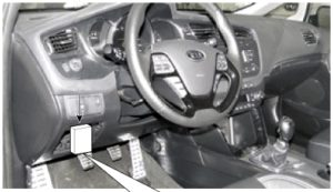
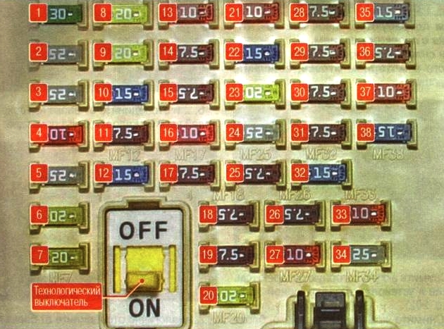
Cabin block
It is located at the bottom of the instrument panel behind a protective cover.
Marking on the lid
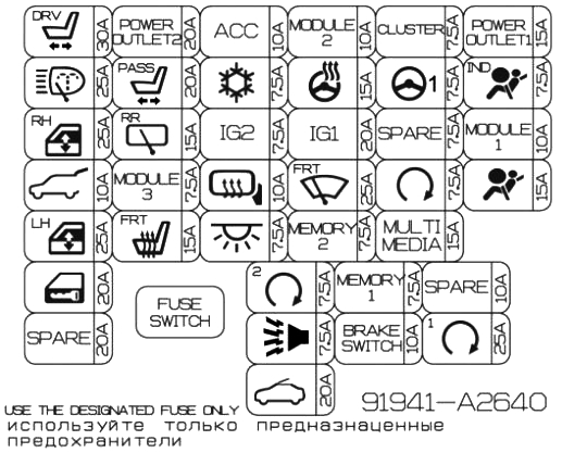
Photo – diagram
Description
| 1 | 30A Driver’s seat power drive – P/SEAT DRV |
| 2 | 25A Headlight washer – H/LP WASHER |
| 3 | 25A Power window lifters (right side) – P/WDWRH |
| 4 | 10A Electric tailgate lock drive – T/GATE OPEN |
| 5 | 25A Power window lifters (left side) – P/WDWLH |
| 6 | 20A Central locking – DR LOCK |
| 7 | 20A Spare – SPARE |
| 8 | 20A Cigarette lighter , rear power outlet – POWER OUTLET 2 |
| 9 | 20A Driver’s seat power drive – P/SEAT ASS |
| 10 | 15A Rear door window wiper – RR WIPER |
| 11 | 7.5A Automatic headlight system, automatic transmission selector lock, hazard warning switch – MODULE 3 |
| 12 | 15A Heated front seats – S/HEATER FRT |
| 13 | 10A Audio system, clock, keyless entry system, body electrical control unit (BCM), power exterior mirrors – ACC |
| 14 | 7.5A Air conditioner – A/CON |
| 15 | 7.5A Headlight washer, rain sensor, body electrical control unit (BCM), automatic mirror dimming system, electric sunroof, keyless entry system, heated front seats – IG2 |
| 16 | 10A Heated exterior mirrors, air conditioning – HTD MIRR |
| 17 | 7.5A Interior lighting – INTERIOR LAMP |
| 18 | 7.5A Keyless entry system, engine start/stop button – PDM2 |
| 19 | 7.5A Anti-theft alarm – B/HORN |
| 20 | 20A Electric sunroof drive – SUNROOF |
| 21 | 10A Electric parking brake, electric headlight range adjustment, air conditioning, parking assistance system, headlights, automatic transmission selector lever position indicator, instrument panel switch illumination, front seat heating – MODULE 2 |
| 22 | 15A Heated steering wheel – HTDSTRG |
| 23 | 20A Fuse and relay block in the engine compartment – IG1 |
| 24 | 25A Windshield wiper, rain sensor – WIPER |
| 25 | 7.5A Immobilizer – MEMORY 2 |
| 26 | 7.5A Electric exterior mirrors, central locking, instrument cluster, air conditioning, tire pressure monitoring system, parking assistance system, ignition switch illumination, body electrical equipment control unit (BCM) – MEMORY 1 |
| 27 | 10A Keyless Entry System, Brake Lights BRAKE SWITCH |
| 28 | 7.5A Instrument cluster, clock – CLUSTER |
| 29 | 7.5A Electric power steering – POWER STEERING |
| 30 | 7.5A Reserve – SPARE |
| 31 | 7.5A Starter, ignition switch, automatic transmission selector position sensor, automatic transmission control unit – START |
| 32 | 15A Audio system, clock – MULTI MEDIA |
| 33 | 10A Reserve – SPARE |
| 34 | 25A Keyless Entry System – PDM 1 |
| 35 | 15A Front Power Outlet – P/OUTLET 1 |
| 36 | 7.5A Instrument cluster – A/BAG IND |
| 37 | 10A Body control unit (BCU), tire pressure monitoring system, automatic transmission selector, audio system, automatic headlight control system, lane departure warning system – MODULE 1 |
| 38 | 15A SRS passive safety system – A/BAG |
Fuse 8 at 20A is responsible for the cigarette lighter.
Blocks under the hood
Main unit
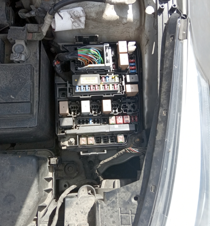
The main fuse and relay block is located in the left side of the engine compartment.
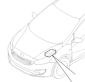
Location example
Block cover diagram
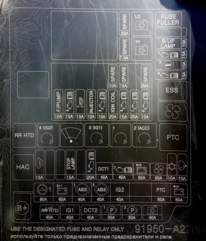
Photo – diagram
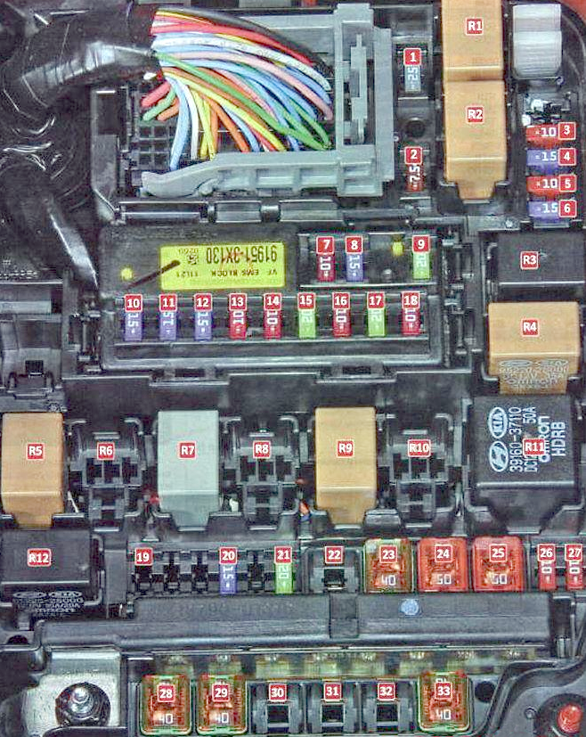
Fuse designations
| 1 | 25A Reserve – SPARE |
| 2 | 7.5A Reserve – SPARE |
| 3 | 10A Reverse light – B/UPLP |
| 4 | 15A Electronic engine control unit, immobilizer, keyless entry system – ECU4 |
| 5 | 10A Anti-lock braking system ABS, ESC stability control system – ABS3 |
| 6 | 15A Electronic control unit for automatic transmission, brake lights – TCU2 |
| 7 | 10A Reserve – SPARE |
| 8 | 15A Reserve – SPARE |
| 9 | 20A Reserve – SPARE |
| 10 | 15A Fuel Pump – F/PUMP |
| 11 | 15A Electronic engine control unit – ECU3 |
| 12 | 15A Sound signals – HORN |
| 13 | 10A Fuel pump – INJECTOR |
| 14 | 10A Electronic engine control unit – ECU2 |
| 15 | 20A Ignition Coils – IGN COIL |
| 16 | 10A Starter, variable valve timing system – ECU9 |
| 17 | 20A Electronic engine control unit – ECU1 |
| 18 | 10A Oxygen sensors, intake manifold length change system, adsorber purge valve – ECU8 |
| 19 | 15F Heated windshield – DEICER |
| 20 | 15A Brake lights, hill-start assist system – STOP LAMP |
| 21 | 20A Electronic Engine Control Unit – TCU1 |
| 22 | 40A Electronic control unit for automatic transmission – DCT1 |
| 23 | 40A Fuses #10-18 – EMS |
| 24 | 50A Fuse box in the passenger compartment – B+3 |
| 25 | 50A Electric heater fan – BLOWER |
| 26 | 10A Air conditioner – A/CON |
| 27 | 10A Rain sensor – WIPER FRT |
| 28 | 40A Rear window heating – RRHTD |
| 29 | 40A Ignition switch, passenger compartment fuse box – IG1 |
| 30 | 40A Electronic control unit for automatic transmission – DCT2 |
| 31 | 30A Electric parking brake actuator – EPB1 |
| 32 | 30A Electric parking brake actuator – EPB1 |
| 33 | 40A Electric cooling system radiator fan – C/FAN |
Relay purpose
| R1 | Cooling system radiator fan relay (low speed) – LO |
| R2 | Cooling system radiator fan relay (high speed) – HI |
| R3 | Emergency Brake System Relay – ESS |
| R4 | Heater electric fan relay – BLOWER |
| R5 | Rear window heating relay – RR HTD |
| R6 | Ignition system relay – IG2 |
| R7 | Wiper relay – WIPER |
| R8 | Ignition system relay – IG1 |
| R9 | Starter relay – START |
| R10 | Ignition switch relay – ACC |
| R11 | Auxiliary heater relay – PTC |
| R12 | Hill-start assist relay – H/LP LO |
Power fuse block
Located inside the main unit.
Scheme
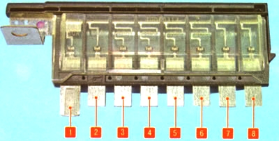
Transcript
- 80A Electric power steering
- 60A Mounting block in the cabin, left headlight unit, cornering lamps, daytime running lights
- 40A ABS anti-lock braking system, ESC stability control system
- 40A ABS anti-lock braking system, ESC stability control system, diagnostic connector
- 40A Ignition switch, starter
- 40A Not used
- 60A Auxiliary heater
- 50A Mounting block in the cabin, right headlight unit, fog lights, tail lights
Additional unit
It is installed mainly on diesel engines.
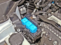
- A: PTC (gasoline) / fuel heater relay (diesel)
- B: Glow plug relay
- C: relay PTK3
- D: relay PTK2
- E: PTK1 relay
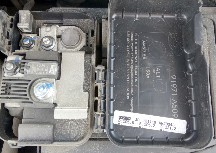
Main fuse
The main power multi-fuse is located on the positive terminal of the battery.
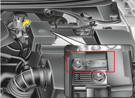
Additional power fuses, in the form of high-power fuse links, may be available nearby.