Kia Rio 3rd generation was produced in 2011, 2012, 2013, 2014, 2015 and 2016 with sedan and hatchback bodies. In our publication you will find a description of fuses and relays Kia Rio 3 with diagrams and photos – examples of execution. We note the cigarette lighter fuse. In conclusion, we suggest you familiarize yourself with the full operating instructions.
Fuse and relay designations may vary. You can find the current diagrams for your Kia Rio 3 on the back of the protective cover.
Cabin block
Located in the cabin under the panel, on the driver’s side, behind a protective cover.

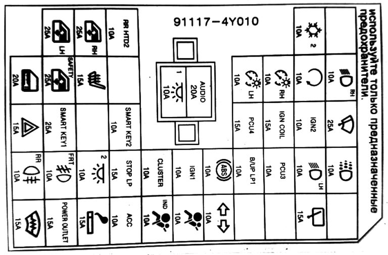
Fuses
Scheme
Description
| 1 | 15A FRT Deicer Windshield Wiper Blade Rest Zone Heater Relay |
| 2 | 15A P/OUTLET Socket for connecting additional equipment |
| 3 | 15A C/LIGHTER Cigarette lighter |
| 4 | 10A ACC Front directional light lamp, power door mirror regulator, BCM, current converter, electronic key ECU, audio system, digital clock, head unit with navigation |
| 5 | 10A A/BAG IND Front airbag deactivation indicator |
| 6 | 10A A/BAG SRS safety system control unit |
| 7 | 10A Hazard warning switch |
| 8 | 10A MOPS 2 ECU EUR |
| 9 | Reserve |
| 10 | 15A R/WPR Rear window wiper and washer (optional) |
| 11 | 15A Steering wheel heater |
| 12 | 10A RR Rear fog lamp relay |
| 13 | 15A FRT Front fog light relay |
| 14 | 10A ROOM 2 Automatic lighting switch-off relay (door opening sensor), switch on the automatic transmission gear lever |
| 15 | 15A STOP LP Relay, brake light switch, electronic key system control unit, electronic key ECU, NAS relay, data link connector |
| 16 | 10A CLUSTER Instrument cluster, VCM unit, audio system, lever illumination, automatic transmission gearshift, tire pressure monitoring module |
| 17 | 10F IGN 1 Brake light switch, heated seats, diagnostic connector, parking sensors |
| 18 | 10A ABS Front panel switch, ESC module, HAC relay |
| 19 | 10A B/UP LP Reverse light switch |
| 20 | 10A PCU Engine control unit, electronic key system control unit, speed sensor, brake light switch, inverter, air conditioning ECU |
| 21 | 10A H/LP LH Left block headlight |
| 22 | 10A DAY TIME RUNNING LIGHT Daytime running lights |
| 23 | 15A HAZARD Alarm relay, VSM |
| 24 | 25A SMK_1 Electronic key control unit |
| 25 | 15A Sunroof motor |
| 26 | 10A SMK_2 Engine start and stop button |
| 27 | 15A PCU Vehicle speed sensor (manual transmission), transmission mode switch (automatic transmission) |
| 28 | 15A IGN COIL Ignition coils, capacitor |
| 29 | 10A IGN Daytime running lights, headlight range control, air conditioning control unit, headlights, power window relay (without VCM), VCM unit, electronic key system control unit (with VCM unit) |
| 30 | 25A F/WPR Windshield wiper, steering column switch |
| 31 | 20A DOOR LOCK Door lock control unit relay (with BCM unit), driver’s door lock actuator (without BCM unit) |
| 32 | 25A SAFETY P/WDW Power window lock |
| 33 | 15A S/HEATER Front seat heating |
| 34 | 10A Electric exterior mirror regulator |
| 35 | 10A ROOM 1 Interior lighting, trunk lighting, air conditioning, tire pressure monitoring module, digital clock |
| 36 | 20A AUDIOS ISG: converter, Without ISG: audio system, head unit with navigation |
| 37 | 10A TAIL LH Rear left lamp, license plate lamps, left headlight unit, instrument panel illumination |
| 38 | 10A TAIL RH Right tail light, right block headlight, instrument panel illumination |
| 39 | 10A START Ignition switch (manual transmission), transmission mode switch (automatic transmission) |
| 40 | 10A H/LP RH Right block – headlight, instrument cluster |
| 41 | 25A P/WDW LHWindow lift control unit, left rear window lift switch |
| 42 | 25A P/WDW RH Window lift control unit, right rear window lift switch |
| 43 | 10A RR HTD Heated exterior rear-view mirror system, EBUD/RSMb Air conditioning ECU |
| 44 | 10A A/CON 2 Air conditioner |
| 45 | Reserve |
Fuse number 2 is responsible for additional sockets, and fuse number 3 at 15A is responsible for the cigarette lighter.
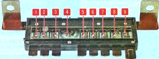
Relay
Non-removable relays are mounted on the back of the unit.
Scheme
Transcript
- Rear window heating relay
- Fog light relay
- Rear fog light relay
- Side light relay
- Daytime running light relay
- Windshield defroster relay
- Door lock relay
- Trunk lid unlock relay
- Turn signal relay
- Alarm relay
- Power window relay
- Security alarm relay
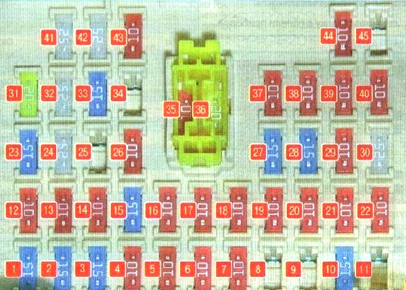
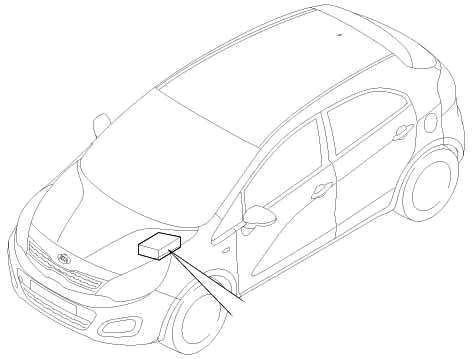
Block under the hood
Located in the left side of the engine compartment.
Example of a circuit from the block cover
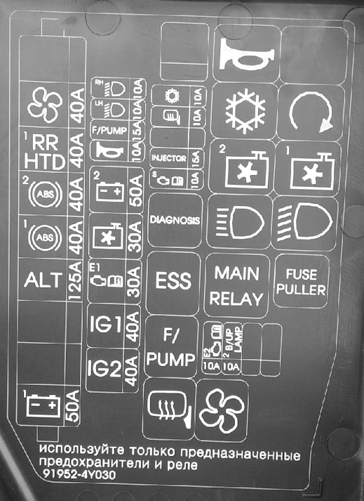
Photo – diagram
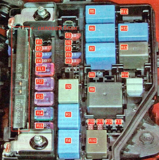
Appointment
| F1 | Reserve |
| F2 | 10A Exterior mirror heating relay |
| F3 | 15A Fuel pump |
| F4 | 10A Audible signal |
| F5 | 10A Air conditioner |
| F6 | Reserve |
| F7 | Reserve |
| F8 | 15A Power supply system (fuel injectors), engine control unit, valve timing solenoid valve |
| F9 | 10A Engine management system sensors, engine control unit, immobilizer module |
| F10 | 10A Fuel and Oil Unit |
| F11 | 10A Reverse light bulbs |
| F12 | Reserve |
| F13 | Reserve |
| FL1 | 50A Instrument panel junction box |
| FL2 | 30A Engine cooling fan relay (high, low speed) |
| FL3 | 30A Engine control unit relay |
| FL4 | 40A Electronic key system control unit relay, ignition switch (without electronic key system) |
| FL5 | 50A Engine start relay (electronic key system), ignition switch (without electronic key system) |
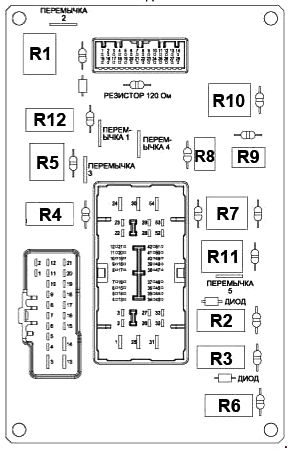
| R1 | Reserve |
| R2 | Emergency braking warning system relay |
| R3 | Fuel pump relay |
| R4 | Exterior rearview mirror heating relay |
| R5 | Horn relay |
| R6 | Air conditioner relay |
| R7 | Fan relay (low speed) |
| R8 | Reserve |
| R9 | Electronic engine control unit relay |
| R10 | Electric fan relay for air heater blower |
| R11 | Reserve |
| R12 | Ignition lock switch relay |
| R13 | Fan relay (high speed) |
| R14 | Reserve |
On the back of the unit there may be some relay elements: a sound signal relay, a security alarm siren relay, a starter relay, etc.
Relay power unit
It is located on the left side of the main unit.
Scheme
Marking
- 50A Instrument panel junction box, tail light relay
- Reserve
- Reserve
- 125A Generator
- 40A ABS hydro-electronic module, diagnostic connector
- 40A ABS Hydroelectronic Module
- 40A Rear window heating relay
- 40A Electric air fan relay heater blower
- Reserve