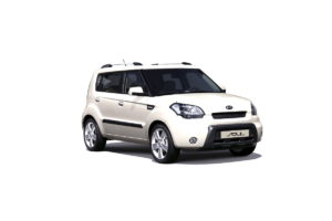
Kia Soul 1st generation was produced in 2008, 2009, 2010, 2011, 2012 and 2013 with both diesel and gasoline engines. During this time, namely at the end of 2011, this model underwent an update, which affected both the appearance and technical modernization. In our article you will find information with a description of fuses and relays Kia Soul 1st generation with block diagrams, locations and photos
Cabin block
Located at the end of the instrument panel behind a protective cover.
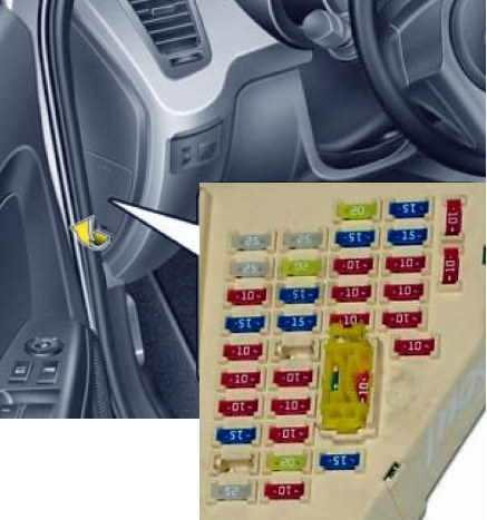
Scheme
Description
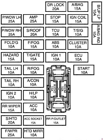
| P/WDW LH | 25A Main switch for electric window lifts, electric window lift switch for the rear left door |
| P/WDW RH | 25A Main switch for electric windows, rear right door electric window switch, passenger door electric window switch |
| PDM 2 | 10A Start/Stop Switch, PDM, Key Fob Holder |
| FOLD’G | 10A Data connector, exterior mirror power switch |
| HAZARD | 15A Hazard warning relay, one-touch turn signal interrupter, hazard warning switch |
| TAIL LH | 10A License plate lights, rear left combination lamp, left headlight |
| TAIL RH | 10A Rear right combination lamp, right headlight, backlight |
| IG 2 | 10A BCM, headlight range control switch, left/right headlight range control actuator, sunroof control unit |
| RR WIPER | 15A Instrument panel junction box (rear window wiper relay), multifunction switch, rear window wiper motor |
| F/CPR | 25A Front wiper motor, multifunction switch, fuse block and M/O relay (relay 10) |
| AMP | 25A With ISG: Low voltage DC to DC converter of ISG system (amplifier) Without ISG: amplifier |
| S/ROOF | 20A Top hatch control unit |
| F/FOG | 15A Front fog light relay |
| T/GATE | 15A Trunk lid relay, diagnostic connector |
| R/FOG | 10A Rear fog light relay |
| A/CON | 10A Air conditioning control unit, engine compartment relay and fuse block (relay 1, relay 5, relay 6), DSL relay and fuse block (relay PTK2, relay PTK3) |
| H/LP | 10A PDM (Headlight low beam relay) |
| ASV | 10A PDM, audio system, amplifier, ISG low voltage DC to DC converter (audio system/amplifier), decorative lighting module, BCM, electronic key control unit, power exterior mirror switch |
| ACC SOCKET | 15A Front power socket, cigarette lighter |
| HTD MIRR | EBUD/PCM, driver/passenger side power exterior mirror motor, air conditioning control unit |
| DR LOCK | Door lock relay, door unlock relay, double lock relay |
| STOP | 15A Stop signal switch, stop signal relay, engine compartment relay and fuse block (relay 8, multi-function diagnostic connector) |
| TCU | 10A Vehicle speed sensor (manual transmission), transmission range switch (automatic transmission), BUT (G4FC/G4FD), ATM lever indicator |
| ABS | 10A ESP switch, steering angle sensor, ABS/ESP control unit, multi-function diagnostic connector |
| IG 1 | 10A Engine compartment relay and fuse block (relay 8, relay 9), brake light switch, oil pump inverter, parking aid system unit, front left/right seat heater, ISG low voltage DC to DC converter (audio system), front left/right seat heater switch, seat belt reminder unit, electro chrome mirror, SBR indicator, reverse parking aid buzzer, ISG switch, tire pressure monitoring unit |
| RR P/OUTLET | 15A Rear power socket, cigarette lighter |
| A/BAG | 15A SRS control unit, passenger airbag indicator |
| IGN COIL | 15A G4FC/G4FD: Ignition coil #1~4, capacitor |
| T/SIG | 10A Emergency alarm switch, multi-function switch |
| CLUSTER | 10A BCM, air conditioning control unit, PDM, electronic key control unit, instrument cluster |
| ECU | 10A EBUD/PCM, air flow sensor, engine compartment relay and fuse block (relay 2), fuel filter status notification sensor |
| START | 10A PDM, transmission range switch, ignition lock switch, EBUD / PCM |
| B/UP LP | 10A Reverse light switch |
| A/BAG IND | 10A Instrument cluster (indicators) |
| AUDIO | 15A RF receiver, with ISG: Low voltage DC to DC converter ISG system (audio system), without ISG: Audio system |
| ROOM | 10A BCM, ignition switch light and door opening sensor, instrument cluster, tire pressure monitoring module, air conditioning control unit, right/left sun visor lamp, center interior light bulb, directional light bulb, power exterior mirror switch |
The front cigarette lighter fuse is labeled ACC SOCKET, and the rear one is labeled RR P/OUTLET.
Behind the fuse box, under the panel, a separate power distribution module relay block is installed, which is responsible for the start/stop button and its backlight.
Blocks under the hood
Main unit
Located on the left side of the engine compartment, next to the battery.
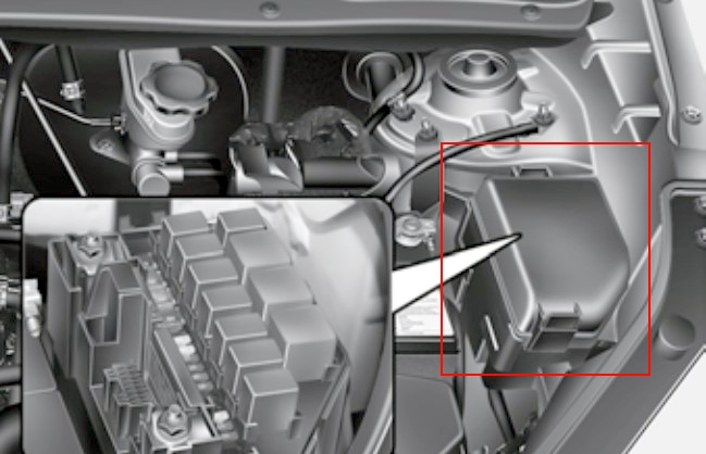
Option 1
Photo example
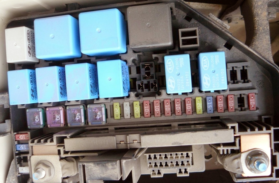
Diagram with notation
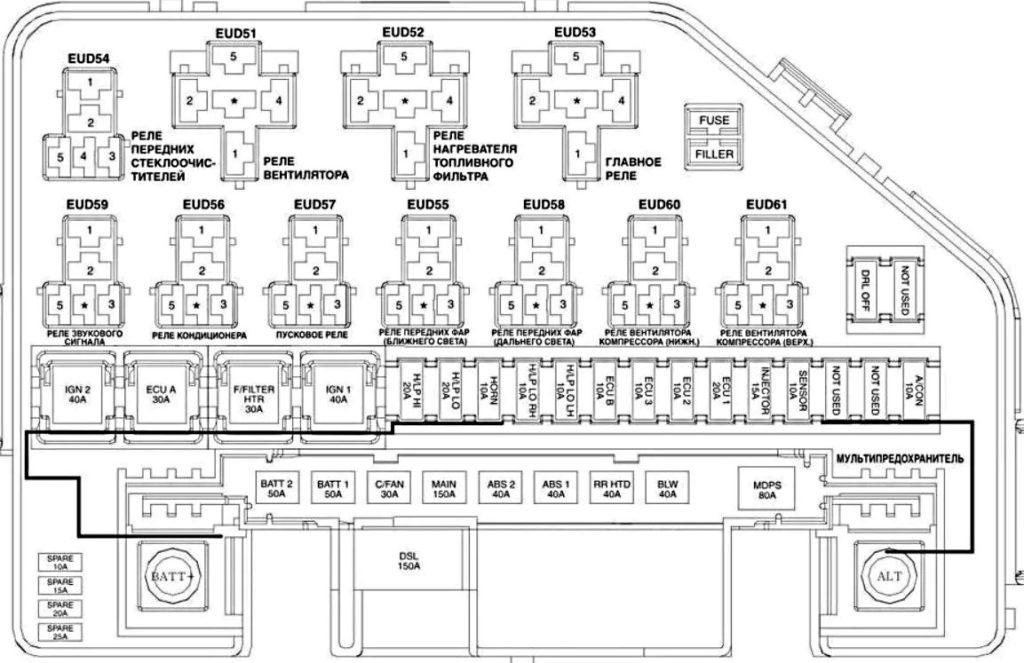
Appointment
| OJSC 2 | 50A Junction box l/P (relay – rear parking lights, fuses – TAIL LH 10A. FOG 10A, power connectors – ROOM 10A, AUDIO 15A) |
| OJSC 1 | 50A Junction box l/P (relay – glass servo, fuses – P/WDW LH 25A, P/WDW RH 25A, FOLD’G 10A, HAZARD 15A) |
| C/FAN | 30A Compressor fan relay (upper), compressor fan relay (lower) |
| MAIN | 150A Generator, fuses (ABS 240A, ABS 140A, RR NTO 40A, BLW 40A, MDPS 80A, A/CON 10A, DSL 150A) |
| ABS 2 | 40A ABS control module, ESP control module |
| ABS 1 | 40A ABS control module, ESP control module |
| RRHTD | 40A Junction box I/P (rear window defroster relay) |
| BLW | 40A Fan Relay |
| MDPS | 80A EPS Control Module |
| DSL | 150A Relay and Fuse Block DSL (GLOW 80A, RTS 1 50A, RTS 2 50A, RTS 3 50A) |
| IGN 2 | 40A Ignition switch, starter relay |
| ECU A | 30A Main relay, ECU B10A |
| F/PUMP | 20A G4FC: Fuel pump relay |
| F/FILTER HTR | 30A D4FB: Fuel filter heater relay |
| IGN 1 | 40A Ignition switch |
| H/LPHI | 20A Headlight relay (high beam) |
| H/LPLO | 20A Headlight relay (low beam) |
| HORN | 10A Horn Relay |
| HORN | 10A Horn Relay |
| H/LP LO RH | 10A Right headlight |
| H/LP LO LH | 10A Left headlight, instrument panel (low beam indicator) |
| ECU B | 10А D4FB: TCM G4FC: ECM, PCM |
| ECU 3 | 10A D4FB:Fuel pressure control valve |
| ECU 2 | 10A D4FB: Brake light switch |
| ECU 1 | 20А D4FB: ЄСМ G4FC: ECM, PCM |
| INJECTOR | 15A D4FB: DSL (Glow Relay, PTC 1 Relay, PTC 2 Relay, PTC 3 Relay) Relay and Fuse Block, Camshaft Position Sensor, EGR (Exhaust Gas Recirculation) Actuator, Variable Geometry Turbocharger (VGT) Actuator, Immobilizer Module G4FC: Injectors No. 1~4, Idle Control Actuator, Immobilizer Module, Fuel Pump Relay |
| SENSOR | 10A D4FB: Air conditioner relay, compressor fan relay (upper/lower), oxygen sensor, air heater relay G4FC : ECM |
| A/CON | 10A Air conditioner relay |
| DRL OFF | 10A VSM |
Option 2
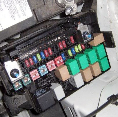
Scheme
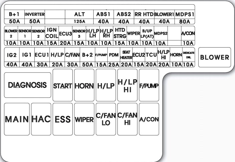
Transcript
| B+ 1 | 50A I/P Junction Box (Power Window Relay, Fuses – P/WDW LH 25A, P/WDW RH 25A, PDM 2 10A, HAZARD 15A) |
| INVERTER | 50A Oil Pump Inverter |
| ALL | 125A Generator, fuse (ABS 240A, ABS 140A, RR HTD 40A, BLOWER1 40A, MDPS 80A, A/CON 10A) |
| ABS 1 | 40A ESC Module |
| ABS 2 | 40A ESC Module |
| RR HTD | 40A Junction box I/P (rear heater relay) |
| BLOWER 1 | 40A Fan Relay |
| MDPS 1 | 80A EPS Control Module |
| IG 2 | 40A Ignition switch, PDM relay block (IG 1 Realy), start relay |
| IG 1 | 40A Ignition switch, PDM relay box (IG 2 Realy) |
| ECU 1 | 30A Engine Control Relay |
| H/LP | 20A Headlight Relay |
| C/FAN | 30A Air Conditioner Fan Relay |
| B+2 | 50A Junction Box I/P (Tail Light Relay, Fuse – TAIL LP LH 10A, TAIL LP RH 10A, 20A SAMPLE, AMP 25A, DR LOCK 20A, LP 15A, T/GATE OPEN 15A, Power Connector – ROOM LP 10A, MODULE 15A) |
| F/PUMP | 15A Fuel pump relay |
| PDM | 25A PDM, Smart Key control module |
| SEAT HEATER | 20A Heated driver’s seats, Heated passenger seats |
| ECU 2 | 15А PCM/ECM |
| TCU | 20A PCM |
| H/LP HI | 20A Headlight Relay |
| HORN | 10A Signal Relay |
| DEDICATE DRL | 10А BCM |
| BLOWER 2 | 10A Air Conditioning Control Module (Auto) |
| SENSOR 1 | 10A Camshaft position sensor #1/#2, oil control valve #1/#2, canister control valve, air conditioning relay, immobilizer module |
| SENSOR 2 | 10A C / Fan Hl / Low Relay, Injector No. 1 – No. 4 |
| IGN COIL | 15A Ignition coil No. 1 ~ No. 4, capacitor |
| ECU 3 | 20А PCM/ECM |
| SENSOR 3 | 15A Oxygen sensor (up/down), fuel pump relay, purge control solenoid valve, variable air flow solenoid valve |
| H/LP LH | 10A Left headlight |
| H/LP RH | 10A Right headlight |
| HTD STRG | 15A Heated steering wheel |
| WIPER | 10А PCM |
| B/UP LP (AP) | 10A Electro-chromic mirror, rear left/right combination lamp, instrument cluster, A/V and navigation head unit, audio |
| MDPS2 | 10A EPS Control Module |
| A/CON | 10A Air Conditioning Compressor Relay |
Additional unit
Installed on the Kia Soul model with a diesel engine.
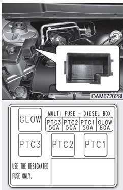
Here are the elements responsible for the operation of additional heating and glow plugs.