The subcompact car Hyundai Getz was produced in 2002, 2003, 2004, 2005, 2006, 2007, 2008, 2009, 2010 and 2011. During this time, the model was restyled, although some call it the second generation. In this publication, you will find a description of the fuses and relays of the Hyundai Getz with block diagrams and their locations. Note the fuse responsible for the cigarette lighter.

The design of the blocks and the purpose of the elements in them may differ and depend on the engine type and the level of equipment of your Hyundai Getz. Check the description with the diagrams on the back of the protective cover.
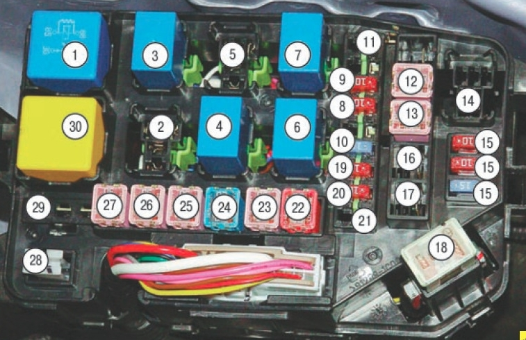
Block in the cabin
It is located under the instrument panel on the driver’s side behind a protective cover.
Photo – diagram
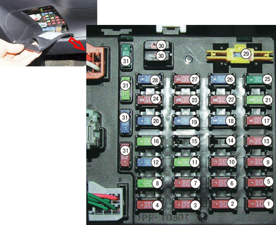
Description of fuses
| 1 | 10A Air Conditioner Switch, Rear Window Defogger Switch |
| 2 | 10A Left front parking light, left rear light |
| 3 | 10A Instrument cluster |
| 4 | 10A Audio system, electric outside rearview mirror switch |
| 5 | 10A Automatic transmission selector switch, reverse light switch, hazard warning light switch |
| 6 | 10A Right front parking light, right rear light, left (right) license plate light |
| 7 | 10A Pre-excitation resistor. Instrument cluster. ECU time delay and security alarm. Seat belt alarm timer. |
| 8 | 15A Cigarette Lighter |
| 9 | 10A Generator, Electric Power Steering ECU, Engine and Transmission ECU (except 1.1L engine), Engine ECU (1.1L engine), Vehicle Speed Sensor, Automatic Transmission Selector Lever Switch |
| 10 | 10A Airbag ECU |
| 11 | 20A Door lock relay, door lock release relay, sunroof control unit, driver’s door lock actuator |
| 12 | 15A Rear Window Wiper Motor, Steering Column Switch Unit |
| 13 | 10A Starter Relay, Security Alarm Relay |
| 14 | Reserve |
| 15 | 10A Daytime Running Lights Control Unit |
| 16 | 20A Left (right) front seat heating switch |
| 17 | 10A Rear window heating switch. Engine control unit, electric drive and heating of the outside rearview mirror on the driver (passenger) side |
| 18 | 15A Ignition coil, capacitor |
| 19 | 15A Power Window Relay, Brake Light Switch |
| 20 | 15A Hazard warning switch, time delay and security alarm control unit |
| 21 | 20A Windscreen Wiper Motor, Steering Column Switch Unit |
| 22 | 10A Rear Fog Light Relay |
| 23 | 10A Fog lamp relay. Window lifter relay. Time delay and security alarm control unit, rear window heating timer, left (right) headlight corrector electric drive, headlight corrector switch |
| 24 | 10A Interior Fan Relay, Sunroof Control Unit |
| 25 | 30A Rear Window Heating Relay, Rear Window Heating Timer, Time Delay and Security Alarm Control Unit |
| 26 | 15A Right headlight |
| 27 | 10A Fog Light Relay |
| 28 | 10A Left headlight, instrument cluster |
| 29 | 15A Instrument cluster, rear fog light switch, data line connector, audio system. Time delay and alarm ECU. Door ajar indicator light sensor, universal test connector, luggage compartment light, interior spotlights, interior light, roof console unit |
| 30 | Tweezers |
| 31 | Spare |
Fuse number 8, 15A, is responsible for the cigarette lighter.
Relays are attached to the back of the block.
Relay diagram
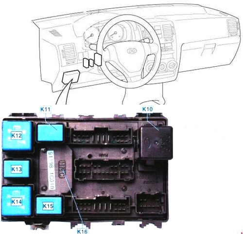
Purpose of the relay
- K10 – Relay-interrupter of direction indicators and hazard warning lights
- K11 – Fog light relay
- K12 – Rear door glass heating relay
- K13 – Parking light lamp relay
- K14 – Window lifter relay
- K15 – Rear fog light relay
- K16 – Control unit for external lighting during daytime driving
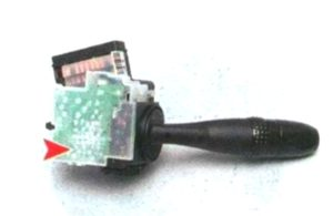
The wiper and washer relay is located separately in the right steering column switch.
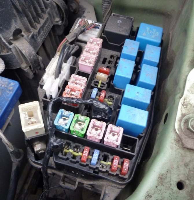
Block under the hood
It is located on the left side of the engine compartment.
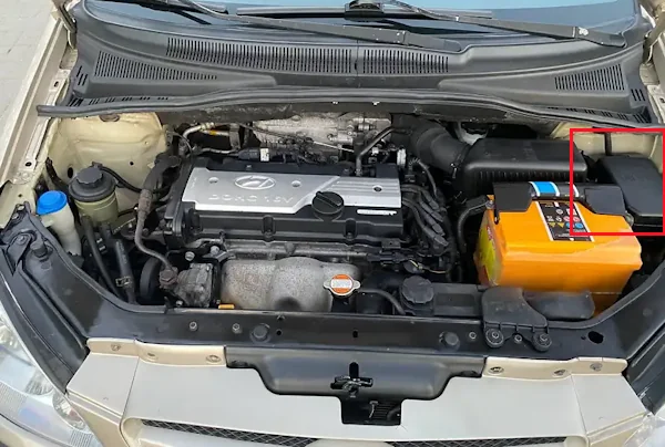
Photo – example of execution
Scheme from the block cover
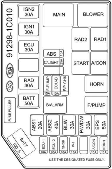
Relay designation
- 1 – Interior heater fan relay E 51
- 2 – place for the relay for switching on the engine cooling system fan at high speed E 44
- 3 – relay for switching on the engine cooling system fan at low speed E 43
- 4 – starter relay E 41
- 5 – place for air conditioner relay E 50
- 6 – horn relay E 45
- 7 – fuel pump relay E 49
- 14 – place for the E 47 alarm relay
- 30 – power supply relay for the electronic engine management system E 42
Decoding fuses
| 8 | 10A A/CON – Air Conditioner |
| 9 | 10A HORN – Horn |
| 10 | 15A INJ – Engine ECU, injectors, camshaft position sensor, crankshaft position sensor, idle speed control valve, purge solenoid valve of the adsorber |
| 11 | 50A EPS – Electric Power Steering |
| 12 | 30A P/WDW – Electric windows |
| 13 | 30A BLW – Interior Heater Fan |
| 15 | 10/15A SPARE – Spare fuses |
| 16 | 40A ABS. 2 – ABS ECU, air bleed connector |
| 17 | 20A ABS. 1 – ABS ECU, air bleed connector |
| 18 | ALT 120 / 100A – Generator |
| 19 | 10A SNSR – Air Conditioner, Fuel Pump, Immobilizer Antenna Unit, Oxygen Sensor, Fuel Pump Relay, Air Conditioner Relay |
| 20 | 10A ECU – Fuel Pump, ECU Fuse |
| 21 | 10A ABS – ABS ECU, Air Bleed Connector |
| 22 | 50A BATT – Tail lights, fuses 11, 19, 20, 25, 27, 29 |
| 23 | 30A RAD – Radiator Fan Cooling System |
| 24 | 20A F/PUMP – Automatic Fuel Shut-Off Switch |
| 25 | 30A ECU – Fuel pump, generator, electronic control unit |
| 26 | 30A ING 1 – Ignition switch, starter relay |
| 27 | 30A ING 2 – Ignition switch |