Hyundai Elantra 3rd generation, also known as Elantra xd was produced in 2000, 2001, 2002, 2003, 2004, 2005 and 2006 with both diesel and gasoline engines. In this publication you will find a description of the fuses and relays of the Hyundai Elantra 3 with block diagrams and photo examples of execution. Let’s highlight the cigarette lighter fuse.
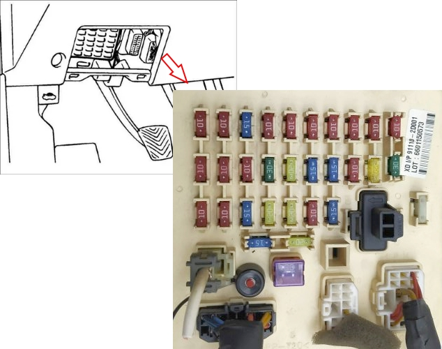
Cabin block
It is located under the panel on the driver’s side behind a protective cover.
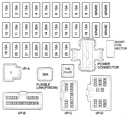
Description
| 1 | 10A Turn signals, reversing lamps |
| 2 | 10A Instrument panel lighting, DRL, generator, wiper delay unit, standard alarm system |
| 3 | 15A Airbags |
| 4 | 10A Emergency alarm |
| 5 | 10A Interior heater motor |
| 6 | 10A Front right headlight, interior lighting |
| 7 | 10A Front left headlight, exterior lighting |
| 8 | 10A Standard alarm, starting circuit |
| 9 | 10A Clock, electric mirrors, audio |
| 10 | 10A Cruise control, ECU, automatic transmission ECU, speedometer |
| 11 | 10A ABS |
| 12 | 10A Airbag indicator lamp |
| 13 | 30A Heated rear window |
| 14 | 20A Retractable antenna motor |
| 15 | 15A Central locking, sunroof |
| 16 | 15A Brake light bulbs, power windows |
| 17 | 10A Heated rear window and heated side mirrors |
| 18 | 15A Cigarette lighter and 12V socket |
| 19 | 10A Not used |
| 20 | 10A Air conditioning, headlight bulbs, power windows |
| 21 | 15A Rear wiper and washer |
| 22 | 20A Front wiper and washer |
| 23 | 20A Seat heating |
| 24 | 10A Climate control, wiper delay unit, mirror dimming, sunroof |
| 25 | 15A Interior light, trunk light, ignition switch, diagnostic connector, audio |
| Short connector | Jumper. Glove box lighting, audio, climate control |
| P/WDW | 30A Power windows |
| spare | Spare fuses |
Fuse number 18 at 15A is responsible for the cigarette lighter.
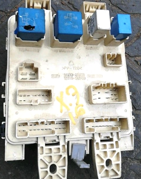
Depending on the configuration, individual relay elements may be located on the back of the unit.
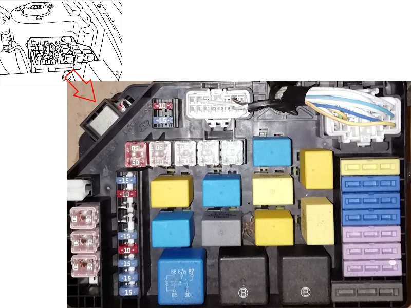
Block under the hood
Main unit
Located in the left part of the engine compartment, next to the battery.
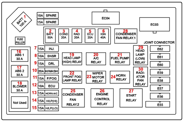
Fuse designations
| 1 | 120A BATT. Main fuse |
| 2 | 50A BATT. Window lifts, tail lights, interior fuses 4, 13 – 16 |
| 3 | 20A COND. Air conditioner radiator fan |
| 4 | 20A RAD. Engine radiator fan |
| 5 | 20A ECU. Generator, ECU, fuel pump |
| 6 | 40A IGN. Ignition, starter |
| 7 | 15A INJ. Injectors, idle speed regulator, adsorber valve, camshaft sensor |
| 8 | 10A SNSR. Oxygen sensor (lambda probe), ECU |
| 9 | 15A DRL. Daytime running lights (low beam when ignition is on) |
| 10 | 20A H/WASH. Headlight washer (not used) |
| 11 | 15A F/FOG. Front fog lights |
| 12 | 10A ECU. Automatic transmission ECU |
| 13 | 15A HORN A/C. Horn, air conditioning |
| 14 | 15A H/LP(HI). High beam |
| 15 | 15A H/LP(LO). low beam |
| 16 | 30A ABS1. Anti-lock braking system (ABS) |
| 17 | 30A ABS2. Anti-lock braking system (ABS) |
| 18 | 30A BLOWER. Interior heater fan |
Relay purpose
| 19 | HEAD LAMP HI High beam lamps |
| 20 | A/C Air conditioning |
| 21 | FUEL PUMP Fuel pump |
| 22 | FRONT FOG LAMP Front fog lights |
| 23 | WIPER MOTOR Wiper motor |
| 24 | HORN Sound signal |
| 25 | CONDENSER FAN 2 Air conditioner radiator fan relay 2 |
| 26 | ENGINE CONTROL ECU |
| 27 | START Starter |
| 28 | CONDENSER FAN 1 Air conditioner radiator fan relay 1 |
| 29 | HEAD LAMP LOW Low beam lamps |
| 30 | RADIATOR FAN Engine radiator fan |
Additional unit
Installed on models with a diesel engine.
Scheme
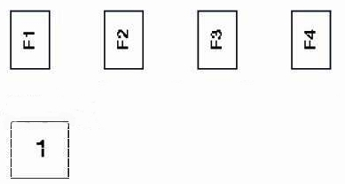
Transcript
- 1 – Glow plug relay
- F1 (30A) – Fuel heater
- F2 (30A) — Coolant heater
- F3 (80A) — Glow plug
- F4 (60A) — Coolant heater