Hyundai Sonata 6 (YF) of the 6th generation was produced in 2010, 2011, 2012, 2013 and 2014. In this publication you will find a description of the fuses and relays of the Hyundai Sonata 6 with block diagrams, photo examples of execution and locations. Let’s highlight the fuse responsible for the cigarette lighter.

Check the purpose of the elements and their parameters in the blocks with your diagrams or other technical documentation.
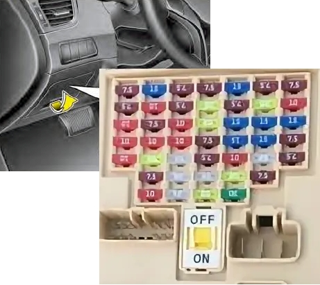
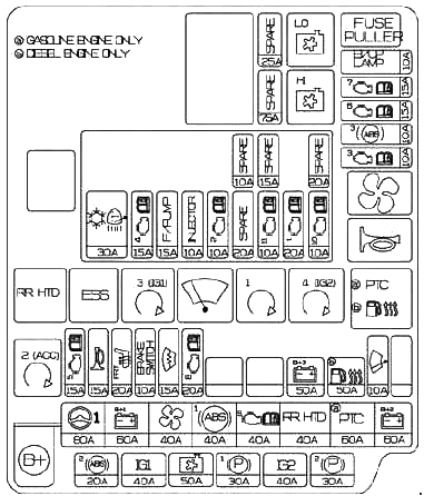
Cabin block
Located under the instrument panel behind a protective cover.
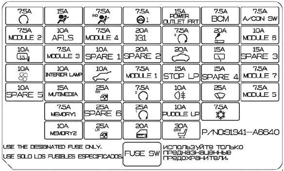
Example of block cover designation
Scheme
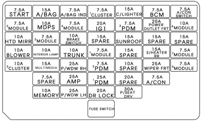
Fuse designations
| START | 7.5A Without Smart Key system: ICM relay block (Alarm relay), With Smart Key system: Automatic transmission mode switch, ECM, E/R fuse and relay block (Start 1 relay), Smart Key system control module |
| A/BAG | 15A SRS passive safety system control module, Occupant mass classification sensor |
| A/BAG IND | 7.5A Instrument panel |
| MDPS | 7.5A EPS Power Steering Control Module |
| POWER OUTLET | 15A Power outlet (sockets) |
| BCM | 7.5A Smart Key System Control Module, BCM |
| A/CON SW | 7.5A Air conditioning control module |
| MODULE 2 | 7.5A Electro chrome mirror, ESC system switch |
| SPARE 1 | Reserve |
| MODULE 4 | 7.5A Rear parking assist sensor Left/Right (Inner/Outer), Air conditioning control module (Climate control), Automatic transmission selector position indicator |
| IG1 | 20A Fuse and Relay Box E/R (Fuse – TCU 1, ECU 3, ABS 3) |
| PDM3 | 7.5A Smart Key system control module |
| C/LIGHTER | 20A Cigarette lighter |
| MODULE 6 | 10A Outside mirror adjustment switch, Audio, Audio and navigation head unit module, Digital clock |
| HTD MIRR | 10A Outside mirror adjustment switch Driver/Passenger, Air conditioning control module |
| MODULE 3 | 7.5A Audio systems, Tire pressure monitoring system module, Digital clock, BCM, Instrument panel, Driver and passenger seat heating module |
| SUNROOF | 15A Roof hatch |
| S/HEATER RR RH | 15A Rear seat heating switch, Right |
| BLOWER | 10A Air Conditioning Control Module (Manual Air Conditioning), ECM/PCM, Blower Resistor |
| IOD 1 | 10A Trunk lamp, Individual lighting lamp Left/Right, Interior lamp, Overhead console lamp, Ignition switch III. and Door ajar warning switch (Without Smart Key system) |
| TRUNK | 10A Trunk lid relay |
| MODULE 1 | 7.5A Transmission shift to Sport mode (automatic transmission), Key solenoid (Without Smart Key system) |
| S/HEATER RR LH | 15A Rear seat heating switch, Left |
| MODULE 7 | 7.5A Smart Key System Control Module, BCM |
| IOD 2 | 20A Audio Systems, A/V and Navigation Head Unit Module |
| P/WDW RH | 25A Power window relay, Right |
| PDM2 | 7.5A Smart Key System Control Module, Start Stop Button Switch |
| WIPER FRT | 25A Fuse and Relay Block ICM (Rain Sensor Relay), Multifunction Switch, Wiper Motor, Fuse and Relay Block E/R (Wiper Relay) |
| MODULE 5 | 7.5A Ionizer (Climate control), Rain sensor, Sunroof |
| AMP 1 | 25A AMP (amplifier) |
| PDM 1 | 25A Smart Key System Control Module |
| A/CON | 7.5A Air Conditioning Control Module, Fuse and Relay Box E/R (Fan Relay) |
| IOD 4 | 10A Tire Pressure Monitoring System Module, BCM, Auto Headlamp Photo Sensor, Instrument Cluster, DLC, Distribution Block Upgrade Connector, Electro-Chrome Mirror, A/C Control Module, Digital Clock |
| P/WDW LH | 25A Left Window Power Relay, Window Power Security Module |
| DR LOCK | 20A Door Lock Relay, Door Unlock Relay, Fuse and Relay Block ICM (Turn Signal Relay) |
| P/SEAT DRV | 30A Driver’s manual seat adjustment switch |
The fuses marked C/LIGHTER and POWER OUTLET are responsible for the cigarette lighter or additional sockets.
Blocks under the hood
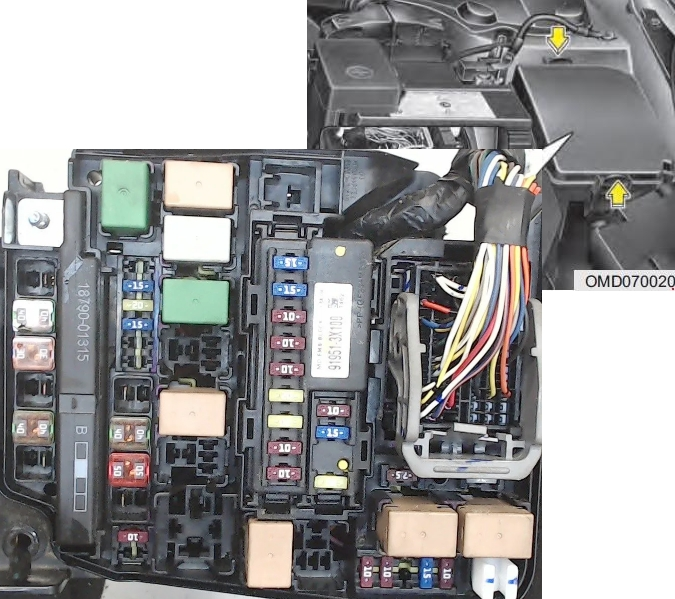
Main unit
Located in the left side of the engine compartment.
Scheme with purpose
Scheme
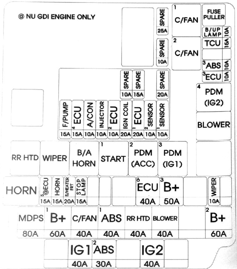
Fuse description
| MDPS | 80A EPS system control module |
| B+1 | 60A Distribution Block (ARISU 1 (4CH), IPS 1, Fuse – P/WDW LH, P/WDW RH, TRUNK, AMP 1) |
| C/FAN | 40A Cooling Fan Relay (Low), Cooling Fan Relay (High) |
| ABS 1 | 40A ESC Module, Multifunctional Diagnostic Connector |
| RR HTD | 40A Seat heating relay |
| BLOWER | 40A Cooling system fan relay |
| B+2 | 60A Distribution block (Turn signal horn relay, ARISU 2 (4CH), IPS (1CH), IPS (2CH), Fuses – P/SEAT DRV, SUNROOF [HATCH]) |
| B/UP LP | 10A Electro Chromium Mirror, Audio/Video (A/V) and Navigation Head Unit Module, Tail Light Combination (Inner) Left/Right, Brake Light Switch, BCM, Instrument Cluster |
| TCU 1 | 15A Vehicle speed sensor, Automatic transmission mode switch |
| ABS3 | 10A ESC system module, Multifunction diagnostic connector |
| ECU3 | 10A Brake light switch, ECM, automatic transmission – PCM |
| WIPER | 10A Rain sensor, ECM, automatic transmission – PCM |
| B+3 | 50A Distribution Block (Fuses – MODULE 1, PDM 1, PDM 2, DR LOCK) |
| EMS | 40A EMS Unit (Engine Control Relay, Fuses – ECU 4, A/CON, F/PUMP) |
| STOP LP | 15A Brake light switch, Smart Key system control module |
| S/HEATER FRT | 20A Driver and passenger seat heating control module |
| HORN | 15A Horn Relay |
| IG2 | 40A Without Smart Key system: Ignition switch, Start relay 1, With Smart Key system: PDM relay 4 (IG2), Start relay 1 |
| ABS 2 | 30A ESC system module, Multifunction diagnostic connector |
| IG 1 | 40A Without Smart Key system: Ignition switch, With Smart Key system: PDM relay 3 (IG1), PDM relay 2 (ACC) |
| F/PUMP | 15A Fuel pump relay |
| ECU 4 | 15A PCM (automatic transmission), ECM (manual transmission) |
| A/CON | 10A Air conditioning compressor relay |
| INJECTOR | 10A Fuel injectors #1 / #2 / #3 / #4, A/C compressor relay, Fuel pump relay |
| ECU 2 | 10A PCM (automatic transmission), ECM (manual transmission) |
| IGN COIL1 | 20A Ignition Coils #1 / #2 / #3 / #4, Capacitor |
| SENSOR 2 | 10A Immobilizer System Module Camshaft Position Sensor #1 /#2 |
| SENSOR 1 | 10A Oxygen Sensor (Upper/Lower), Fuel Tank Auxiliary Shutoff Valve, Intake Manifold Length Solenoid Valve, Variable Valve Timing Oil Pressure Control Valve #1/#2, Evaporative Emission Solenoid Valve, Engine Cooling Fan Relay (Low), Engine Cooling Fan Relay (High) |
| SPARE | Reserve |
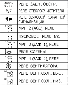
Relay decoding
There may be high-capacity fuses on the positive terminal of the battery.
Additional unit
Installed on diesel models of the Sonata 6 in the right part of the engine compartment.
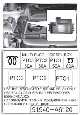
Purpose of elements
- 80A GLOW – glow plugs
- 50A RTS – additional heater / heater