Dodge Sprinter (2003, 2004, 2005, 2006) Fuse Box and Relay Diagram.
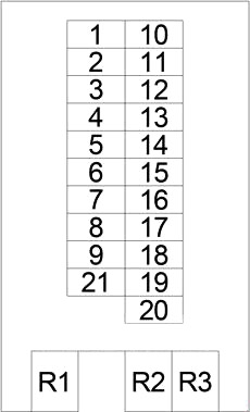
Fuse box #1
| No. | A | The chain is protected |
|---|
| 1 | 10 | Headlight switch |
| 2 | 10 | Right headlight (high beam) |
| 3 | 10 | Left headlight (high beam), instrument cluster |
| 4 | 10 | Shifter assembly |
| 5 | 10 | Brake light switch, data link connector |
| 6 | 20 | Multifunction switch (windshield wiper/turn signal/engine start control module) |
| 7 | 15 | Accessory Relay, Light Relay – Right (Trailer Tow Port, Tail Light, Head Light), Remote Security Key Access Module, Horn (VTSS), Rear Window Defogger Switch, Circulation Pump Relay, Transmission Control Relay, Horn Relay |
| 8 | 20 | Cigarette Lighter, Radio, Auxiliary Heater Switch, Turn Signal/Anti-Theft Alarm Relay – Left/Right, Interior Light, Interior Light, Dome Light |
| 9 | 15 | Multi-function switch (hazard warning switch) |
| 10 | 10 | Map/Reading Lamp Switch, Interior Light Switch, Radio, A/C Fan Switch, Automatic Temperature Control Module, Headlamp Leveling Switch, Hazard Warning Switch, A/C Switch – Roof, Temperature Switch, Shift Assembly, TCS (ASR) Switch, Door Lock Master Switch, Tow/Intrusion Sensor On/Off Switch, Ashtray Lamp, Fog Lamp Switch, Rear Window Defogger Switch, Locker #1 Switch, Cigarette Lighter Lamp |
| 11 | 10 | Left light relay (headlight, taillight) |
| 12 | 10 | Right headlight (low beam), daytime running light relay – right |
| 13 | 10 | Left headlight (low beam), daytime running light relay – left |
| 14 | 15 | Fog light relay |
| 15 | 10 | Radio, Radio / Cellular Antenna, Central Timer Module, |
| 16 | 15 | Engine Control Module |
| 17 | 15 | Engine Control Module, EGR Valve, Crankcase Heater |
| 18 | 15 | Start and Crank Relay, Engine Control Module, Instrument Cluster, Air Bag Control Module |
| 19 | 15 | — |
| 20 | 15 | Circulation pump relay, automatic temperature control module |
| 21 years old | 30 | Fan motor |
| Relay |
| R1 | Engine control |
| R2 | Windscreen Wiper On/Off |
| R3 | Direction indicator |
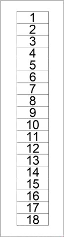
Fuse box #2
| No. | A | The chain is protected |
|---|
| 1 | 10 | Daytime running light relay (instrument cluster, left headlight, right headlight, license plate light, parking light) |
| 2 | 10 | Gearbox control relay |
| 3 | 15 | Dashboard socket |
| 4 | 7.5 | Left lamp relay, right lamp relay |
| 5 | 25 | Central Timer Module |
| 6 | 7.5 | Data link connector, instrument cluster |
| 7 | 25 | Power Window Switch – Driver |
| 8 | 10 | Power Mirror Switch, Driver/Passenger Power Mirror Motor |
| 9 | 15 | A/C Switch – Roof, Rear Window Defogger Module, Central Timer Module, D+#2 Relay, Daytime Running Light Relay, Right Lamp Relay, Auxiliary Battery Relay |
| 10 | 7.5 | Daytime running light relay (right side) |
| 11 | 7.5 | Daytime running light relay (left side) |
| 12 | 25 | Case connector |
| 13 | 15 | Start and run relay |
| 14 | 10 | D + relay 2 |
| 15 | 25 | Power Window Switch – Main, Power Window Switch – Passenger |
| 16 | — | |
| 17 | — | |
| 18 | — | |
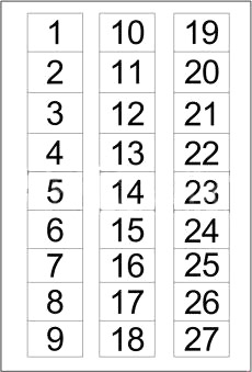
Fuse box #3
| No. | A | The chain is protected |
|---|
| 1 | 7.5 | Additional heater timer |
| 2 | 7.5 | Security system module, siren, intrusion sensor #1 / #2 / #3 |
| 3 | 25 | Additional heater relay |
| 4 | 25 | Cabin heater assembly |
| 5 | 7.5 | Fog light switch |
| 6 | 25 | Trailer Tow Control Module, Trailer Tow Connector |
| 7 | 10 | Circulation pump diode, cabin heater, auxiliary heater relay |
| 8 | 10 | Fan stage 1 relay |
| 9 | 30 | CTEL connector |
| 10 | 15 | Security system module |
| 11 | 25 | Additional warm air heater assembly |
| 12 | 15 | Switch for cabinet #1/#2 |
| 13 | 7.5 | CTEL connector |
| 14 | 7.5 | Security system module |
| 15 | 15 | Driver/Passenger Seat Heating Switch |
| 16 | — | |
| 17 | — | |
| 18 | 15 | Map/reading lamp switch, interior light switch, time delay relay, |
| 19 | 15 | |
| 20 | 15 | Air conditioner fan switch |
| 21 years old | — | |
| 22 | — | |
| 23 | — | |
| 24 | — | |
| 25 | — | |
| 26th year | — | |
| 27 | — | |
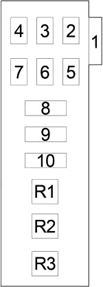
Fuse box #4
| No. | A | The chain is protected |
|---|
| 1 | 30 | Auxiliary air conditioner fan relay |
| 2 | — | — |
| 3 | — | — |
| 4 | — | — |
| 5 | 10 | Remote Access Module with Security Key, Turn Signal/Alarm Relay – Left, Turn Signal/Alarm Relay – Right |
| 6 | 7.5 | ABS |
| 7 | 25 | ABS |
| 8 | 40 | Air Conditioning Control Module – Roof |
| 9 | 40 | ABS |
| 10 | 30 | Rear Window Defogger Module, Rear Window Defogger Relay – Left, Rear Window Defogger Relay – Right |
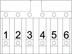
| Relay |
| R1 | — |
| R2 | Starter |
| R3 | — |
Relay block
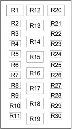
| No. | Relay |
|---|
| R1 | — |
| R2 | Turn Signal / Anti-Theft Alarm – Left |
| R3 | Turn Signal / Anti-Theft Alarm – Right |
| R4 | Lamp – left |
| R5 | Lamp – right |
| R6 | Transmission control |
| R7 | D + №1 |
| R8 | Daytime running light |
| R9 | Fog light |
| R10 | Daytime running light – left |
| R11 | Daytime running light – right |
| R12 | Circulation pump |
| R13 | Launch-Start |
| R14 | Time delay |
| R15 | Auxiliary heater |
| R16 | Additional equipment |
| R17 | Fan Stage 1 |
| R18 | Additional air conditioner fan |
| R19 | — |
| R20 | — |
| R21 | Auxiliary battery |
| R22 | D + №2 |
| R23 | Rear window heating – left |
| R24 | — |
| R25 | Rear window heating – right |
| R26 | — |
| R27 | — |
| R28 | — |
| R29 | — |
| R30 | — |
Fuse block
| No. | A | The chain is protected |
|---|
| 1 | 200 | Generator |
| 2 | 70 | Additional equipment relay (fuse block #2: “6”, “7”, “8”, “15”; fuse block #3: “7”, “12”, “13”, “14”, “15”, “20”; fuse block #4: “6”) |
| 3 | 125 | D + Relay #1 (Fuse Box #2: “9”, “10”, “11”), Fuse Box #2: “1”, “2”, “3”, “4”, “5”, “6”, “12”, “13”, “14”; Fuse Box #3: “1”, “3”, “4”, “5”, “6”, “8”, “9”, “11”, “18”, Fuse Box #4: “1”, “5”, “6”, “7”, “8”, “9”, “10” |
| 4 | 80 | — |
| 5 | 125 | Glow Plug Control Module |
| 6 | 100 | Ignition switch, engine control relay, starter relay, fuse box #1: “6”, “8”, “9”, “17”, “19”, “20”, “21”; fuse box #3: “2”, “10” |