This material provides a detailed look at the fuse box diagrams for the Chrysler Sebring (third generation; JS platform): 2006, 2007, 2008, 2009 and 2010 model years.

Fuses #11, #13 and #16 in the engine compartment block are responsible for the cigarette lighter.
In the engine compartment
Fuse box
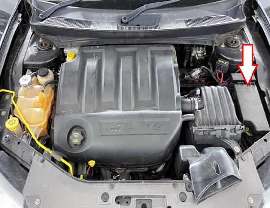
Located next to the air filter housing, under the protective cover.
Example of access.

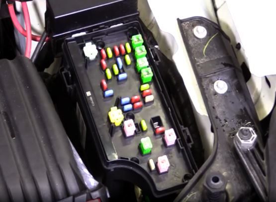
General view.
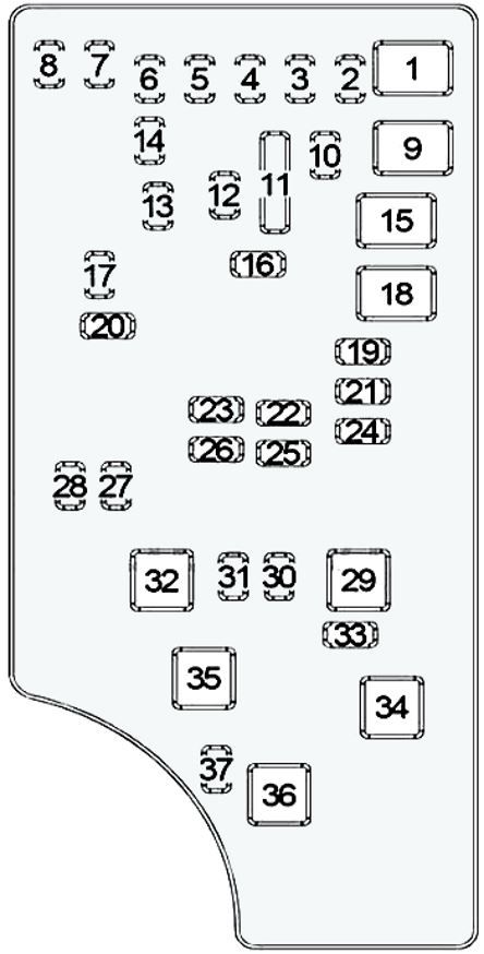
| No. | Description | Current, A |
| 1 | Convertible: Roof Power Module | 40 |
| 2 | All-wheel drive: AWD system | 20 |
| 3 | Brake switch, center high mounted stop lamp | 10 |
| 4 | Ignition switch | 10 |
| 5 | Trailer connector | 20 |
| 6 | Satellite Digital Radio (SDAR), Steering Control Module, IOD Switch, Power Mirror Switch, Climate Control System, Hands-Free System | 10 |
| 7 | IOD – Ignition Off Sensor #1 | 30 |
| 8 | IOD – Ignition Off Sensor #2 | 30 |
| 9 | Secondary air pump (PZEV), driver and passenger seat switch | 40 |
| 10 | Instrument panel, interior electric locks | 20 |
| 11 | Power Outlet – Console | 15 |
| 12 | inverter | 20 |
| 13 | Rear 12V socket | 20 |
| 14 | Interior Lighting, Transceiver Module, Cabin Compartment Node (CCN), Instrument Cluster | 10 |
| 15 | Low or High Speed Radiator Fan Relay, Medium or High Speed Radiator Fan Relay | 40 |
| 16 | Sunroof, Dashboard Socket, Cigarette Lighter Fuse Chrysler Sebring | 15 |
| 17 | Sentry Key Remote Entry System, Steering Control Module (SCM), Wireless Control Module (WCM), Clock | 10 |
| 18 | Main relay | 40 |
| 19 | DVD Video Screen Module, Audio Amplifier #1 and #2 | 20 |
| 20 | Public Address System, Radio | 15 |
| 21 | Siren, Intrus Mod | 10 |
| 22 | Climate control system, cup holder assembly, compass sensor | 10 |
| 23 | Main Relay – Feed #3 | 15 |
| 24 | Sedan – hatch; convertible – roof power module | 25 |
| 25 | Heated mirrors | 10 |
| 26 | Main Relay – Power #2 | 15 |
| 27 | Occupant Presence Recognition Module, Passive Safety System Controller | 10 |
| 28 | 10 | |
| 29 | Empty | – |
| 30 | Heated seats | 20 |
| 31 | Headlight Washer Relay Control Unit | 10 |
| 32 | Main Relay – Power #1 | 30 |
| 33 | Radiator Fan Low/High Speed Relay, Powertrain Control Module, ABS, Switches, Main Relay, Series/Parallel Radiator Fan Relay, Diagnostic Connector, Radiator Fan Medium/High Speed Relay | 10 |
| 34 | Electronic stability control, anti-lock braking system | 30 |
| 35 | 40 | |
| 36 | Driver Door Module (DDM), Headlamp Washer Control Unit, Passenger Door Module (PDM) | 30 |
| 37 | Inverter 110V | 15 |
| Roof module (convertible) | 25 |
Relay block
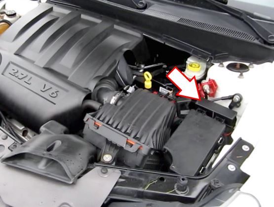
Located next to the fuse box.
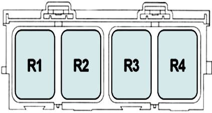
| R1 | Main relay – automatic shutdown |
| R2 | Radiator Fan Low/High Speed Relay |
| R3 | Radiator Fan Relay – Medium or High Speed |
| R4 | Series or parallel radiator fan relay |