The concept of this compact crossover was first presented in 2012 at the Paris Motor Show. Chevrolet Tracker is based on the same platform as Aveo, but unlike its “relative” it offers all-wheel drive and off-road style, for which a large body is responsible, as well as external accessories such as a plastic body kit, roof rails, and a rear diffuser. In this material, we will analyze in detail the fuse diagrams of the Chevrolet Tracker ( Trax ) third generation 2013, 2014, 2015, 2016, 2017, 2018 .

Here you will find the locations and photos of the mounting blocks. We will separately note the fuses responsible for the cigarette lighter and fuel pump.
In the trunk

The unit is located on the left side of the luggage compartment, behind the plastic cover.
| Diagram of the luggage block elements |
|---|
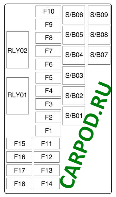
| No. | Description of fuses |
| F1 | PWR LUM SW DR |
| F2 | PWR LUM SW PASS |
| F3 | Amplifier |
| F4 | Trailer socket |
| F5 | AWD SRD |
| F6 | AOS MDL |
| F7 | Spare |
| F8 | Trailer signal st. |
| F9 | Spare |
| F10 | Reserve/SBZA B+ |
| F11 | TRLR MDL |
| F12 | NAV. Doc |
| F13 | Spare |
| F14 | Trailer socket |
| F15 | EVP SW |
| F16 | Fuel heater |
| F17 | ISRVM/RVC |
| F18 | Spare |
| No. | Relay with extended interval |
| SB01 | Electric Seat / SRD Memory |
| SB02 | Spare |
| SB03 | TRLR MDL |
| SB04 | ACDCINV |
| SB05 | AKB+ |
| SB06 | Spare |
| SB07 | Spare |
| SB08 | Spare |
| SB09 | Spare |
| No. | Standard relay |
| RLY01 | Run/Start Relay; |
| RLY02 | Running relay. |
In the salon
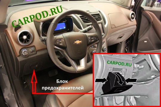
It is located on the driver’s side, behind the glove compartment. To access it, you need to remove the glove compartment.
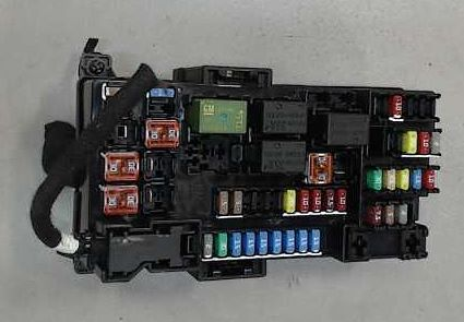
General view of the block.
| Cabin block diagram |
|---|
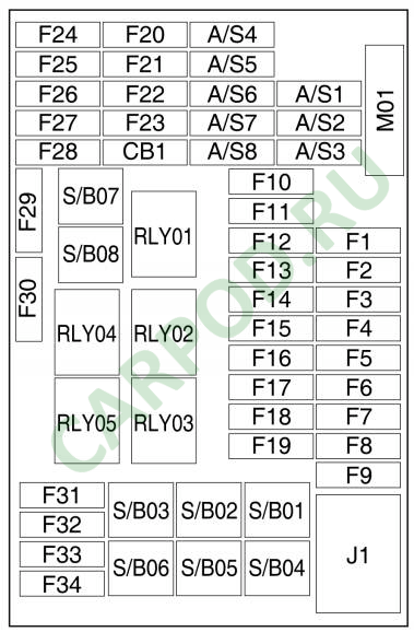
| No. | Transcript |
| RLY01 | BATTERY RELAY/RAP |
| RLY 02 | L/Gate Relay |
| RLY 03 | Spare relay |
| RLY 04 | Blower Fan Relay |
| RLY 05 | Communication mode relay |
| F1 | Body Equipment Control Module 1 |
| F2 | Body Equipment Control Module 2 |
| F3 | Body Equipment Control Module 3 |
| F4 | Body Equipment Control Module 4 |
| F5 | Body Equipment Control Module 5 |
| F6 | Body Equipment Control Module 6 |
| F7 | BCM 7 |
| F8 | Body Equipment Control Module 8 |
| F9 | DLIS |
| F10 | SDM B+ |
| F11 | DLC |
| F12 | HVAC SRD |
| F13 | L/Gate Relay |
| F14 | UPA SRD |
| F15 | Not used |
| F16 | Spare |
| F17 | PWR WNDWSW DR |
| F18 | Rain sensor |
| F19 | BCM RVC |
| F20 | SWC BKLT |
| F21 | AC APO |
| F22 | Cigarette Lighter Fuse / DC APO |
| F23 | Spare |
| F24 | Spare |
| F25 | Spare |
| F26 | AOS display |
| F27 | IPC/CMPS SRD |
| F28 | Headlight Switch/DC Converter/Clutch Switch |
| F29 | Spare |
| F30 | Spare |
| F31 | IPC B+ |
| F32 | RDO/Alarm/AUX socket |
| F33 | Not used |
| F34 | Onstar UHP/DAB |
| SBSB01 | PTC 1 |
| SB02 | PTC 2 |
| SB03 | PWR WNDW MTR BEFORE |
| SB04 | Rear window lift sensor |
| SB05 | Communication mode relay |
| SB06 | Spare |
| SB07 | PWR WNDW BEFORE |
| SB08 | Electric window lift rear |
In the engine compartment
There are two units in the engine compartment: main and additional.
Main fuse box

The main one is located near the battery.

General view.
| Chevrolet Tracker Engine Block Elements Diagram |
|---|
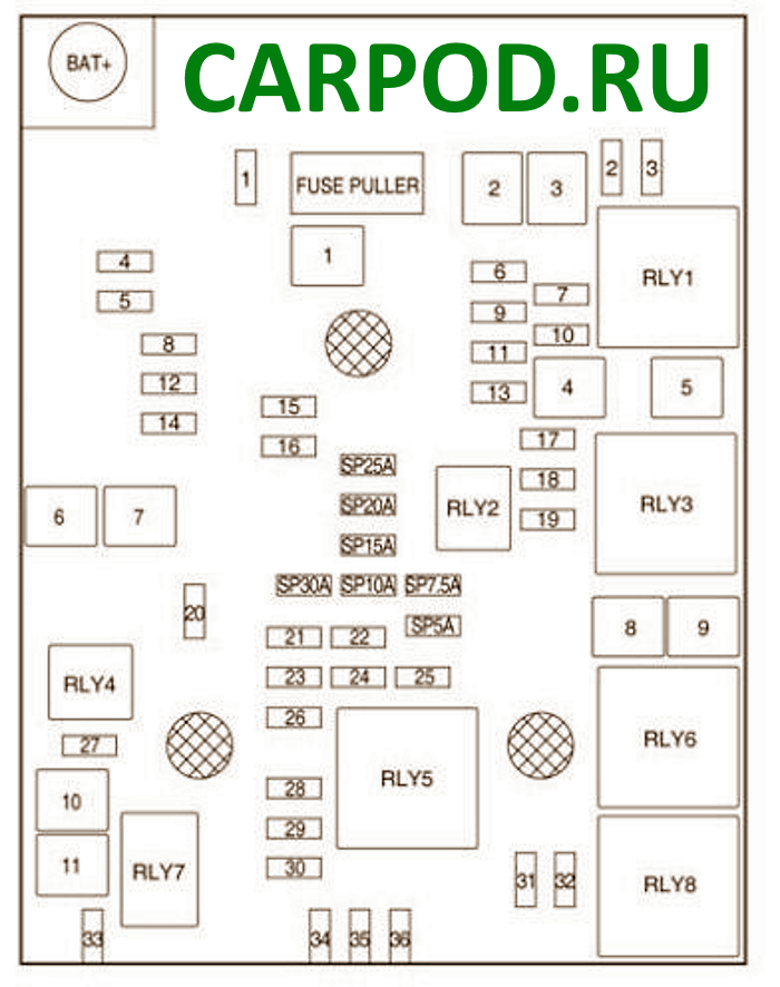
| No. | Fuses type “Mini” |
| 1 | Roof vent |
| 2 | OSRVM SW |
| 3 | Fuel vapor supply valve to the adsorber |
| 4 | Not used |
| 5 | Electronic brake control unit valve |
| 6 | “INTELLIGENT” BRAKING SYSTEM |
| 7 | Not used |
| 8 | TCM B+ |
| 9 | Not used |
| 10 | Headlight tilt adjustment left/right |
| 11 | Rear window cleaner |
| 12 | Rear window defroster |
| 13 | Not used |
| 14 | Heating OSRVM |
| 15 | FSCM B+ |
| 16 | Seat heating module |
| 17 | TCM R/C |
| 18 | ECM R/C |
| 19 | Gasoline pump |
| 20 | Not used |
| 21 | Petrol: FAN RELAY (AUX BEC),Diesel : Fan 3 relay 85 |
| 22 | Not used |
| 23 | Petrol: Ignition/Injector Coil Diesel: ECM PT IGN-2 |
| 24 | Washer pump |
| 25 | Not used |
| 26 | Gasoline: Carbon Canister Purge Solenoid / Water Solenoid / Turbo Boost Pressure Regulator Solenoid / Turbo Boost Wastegate Solenoid / Inlet/Outlet O2 Sensor / IMTV Solenoid |
| Diesel: Swirl control solenoid, piston jet cooling solenoid, engine oil control solenoid | |
| 27 | Not used |
| 28 | Petrol: Not used Diesel: ECM PT IGN-3 |
| 29 | Petrol: ECM PT IGN-1 /IGN-2 Diesel: ECM PT IGN-1 |
| 30 | Gasoline: MAF sensor Diesel: O2 sensor, exhaust particulate sensor |
| 31 | High beam left |
| 32 | High beam right |
| 33 | ECM B+ |
| 34 | Sound signal |
| 35 | Air conditioner clutch |
| 36 | Front fog light |
| No. | Fuse type “Midi” |
| 1 | Electronic brake control unit pump |
| 2 | Front glass wiper |
| 3 | Blower fan |
| 4 | IEC R/C |
| 5 | Not used |
| 6 | Gasoline: Not usedDiesel: Fuel heater |
| 7 | Not used |
| 8 | Low/medium cooling fan speed |
| 9 | high cooling fan speed |
| 10 | Petrol: EVP Diesel: Glow Plug |
| 11 | Starter solenoid valve |
| No. | Purpose of the relay |
| RLY1 | Crankshaft start |
| RLY2 | Fuel pump relay |
| RLY3 | Average cooling fan speed |
| RLY4 | Reserve |
| RLY5 | PT relay |
| RLY6 | Cooling fan speed high |
| RLY7 | Starter |
| RLY8 | Cooling fan speed low |
Additional fuse box
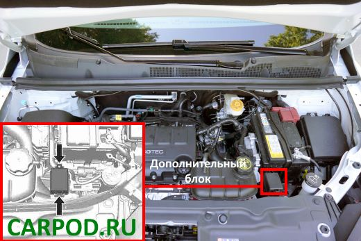
Location
| Scheme |
|---|
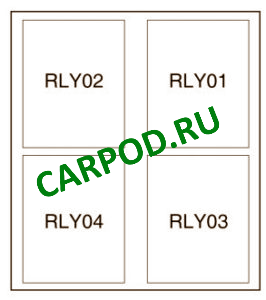
| No. | Description |
| RLY01 | Vacuum Electric Pump Relay |
| RLY02 | Cooling Fan Drive Relay 1 |
| RLY03 | Drive relay 2 cooling fan |